One of the requirements of an ongoing project I’m working on is precisely controlling two brushless motors, this would typically be accomplished by using an off-the-shelf brushless driver like the ODRIVE or the VESC. However, I prefer to start projects from scratch and do things on my own.
I chose to create a new driver, not because the existing ones are insufficient or flawed—in fact, they are probably superior to anything I could create. But simply because "I Can", Seriously though, this project is primarily about the journey; or as someone once said, "The Journey is the Destination." It may take more time (and definitely more money), but the goal of these projects is to have fun while gaining experience (and occasionally pain, lol).
Enough with the talk, so how does it work?
A brushless motor normally needs three half bridges to control the three phases; by turning the coils on and off in a particular order, the motor spins, and by reversing the order, the motor also reverses direction. To determine "what step is the motor currently at," some form of feedback is necessary. This is usually accomplished using hall sensors, an encoder, or, in the case of faster motors, the back-EMF of the coils. I won't go into much detail about brushless motors operation. This DigiKey article does a great job of explaining it.
So, what’s FOC?
?ref=yaseen.ly#/media/File:Diagram_of_a_d,q_coordinate_system_superimposed_on_three-phase_system.jpg)
Recall how I mentioned that the motor would start spinning if we simply followed a switching sequence? Yes, it would, but that isn't the most effective approach.
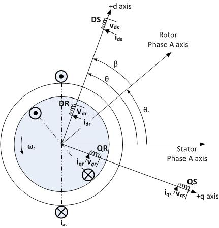
Better efficiency and torque can be obtained using FOC (Field Oriented Control), also known as vector control, by taking into account the direction of the magnetic flux and the current flow. and properly controlling the voltage applied to the coils rather than just switching them on or off.
This comes at the cost of additional hardware requirements and computational power, as we need to be able to measure the current throughout at least 2 phases of the motor. and we need to have a microcontroller fast enough to do the calculations.
I'll go into more detail on the math and theoretical aspects once we start programming the board.
Do I require this for my project? most probably not, but here we are ...
Component Choice
Motor Driver IC
Driving MOSFETs is not easy; they need enough voltage and current (charge) to be able to turn them on and off at high frequencies while also operating outside of their linear region, where they waste a lot of energy as heat since they aren't "completely turned on." In addition, high-side MOSFETs need a voltage at the gate that is higher than the motor supply voltage because the gate voltage needs to be Vgs (generally 10 volts) above the source voltage. Charge pump circuits are typically used to achieve this.
There are numerous specialized ICs designed for this purpose, and even better, many of them include three half-bridge drivers rather than just one, along with other helpful features like built-in current sense amplifiers (that we also require for FOC).
The majority of open-source drivers are based on the DRV8301 or one of its variants, but at the time I started this, obtaining them from a reliable source (not Ali Express) proved challenging. As a result, I kept looking and came across the TMC6200 from Trinamic. There aren't many community projects using this IC, but Trinamic has a set of open-source Evaluation boards that can be used as a reference, and I would say that their Datasheets are very well written.
The TMC2208 and TMC2130 silent stepper drivers, which are utilized by practically all modern 3D printers, are also produced by Trinamic.
Microcontroller
The microcontroller is what’s going to do all the required calculations and sequence control, and choosing one ... was a tough process. Multiple microcontrollers I chose ended up going out of stock during the time I was still designing the PCB, requiring me to switch to a different microcontroller multiple times and some of them went back into stock right when I was done designing the PCB :))
The STM32F446RET6 was the STM32 Microcontroller I ultimately chose to use; it wasn't cheap, but it's a powerful microcontroller with all the features I need, and it also has native USB support, which is kind of a plus. Since this was my first truly "custom" experience with an STM32 microcontroller, it took quite a bit of research and datasheet reading to ensure I chose the correct pins for each purpose, along with choosing the correct crystal frequency and so on. CubeMX/STM32Cube IDE was very helpful during this process.
Power
You'll notice that I don't always choose the best components for this project; instead, I go with what's available. I've previously addressed the chip scarcity several times, but truly.. it made the whole process rather difficult.
I settled on using the LM2576HV buck converter to step down the input to 12V, and two LDOs ( 7805 & AMS1117 ) to step that down to 5V and 3.3V respectively.
MOSFETs
Same story here, I chose something, it goes out of stock, so I pick something slightly less desirable or more expensive.
The BSC028N06NS, which has a RdsON of 0.0028 ohm, is what I ultimately chose to use.
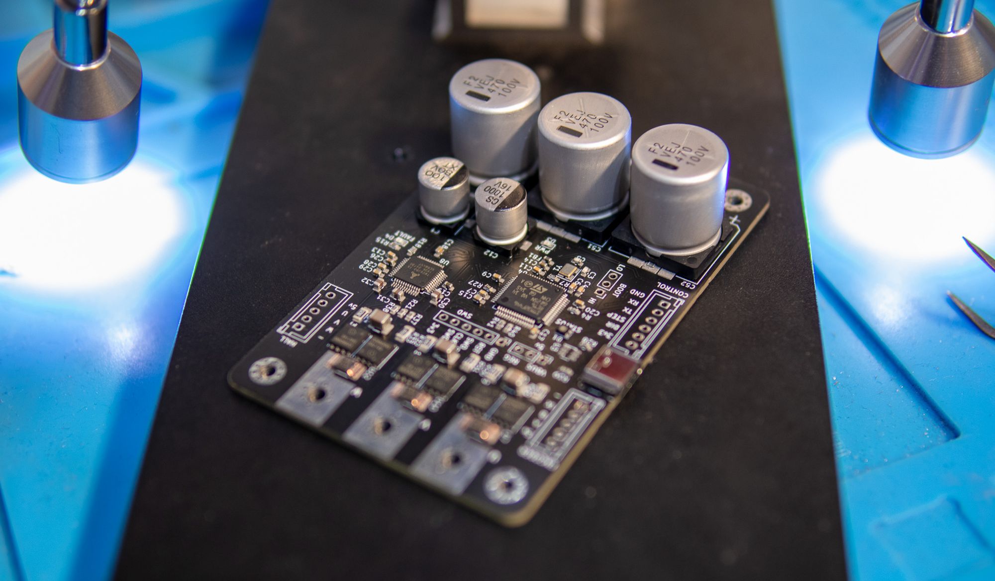
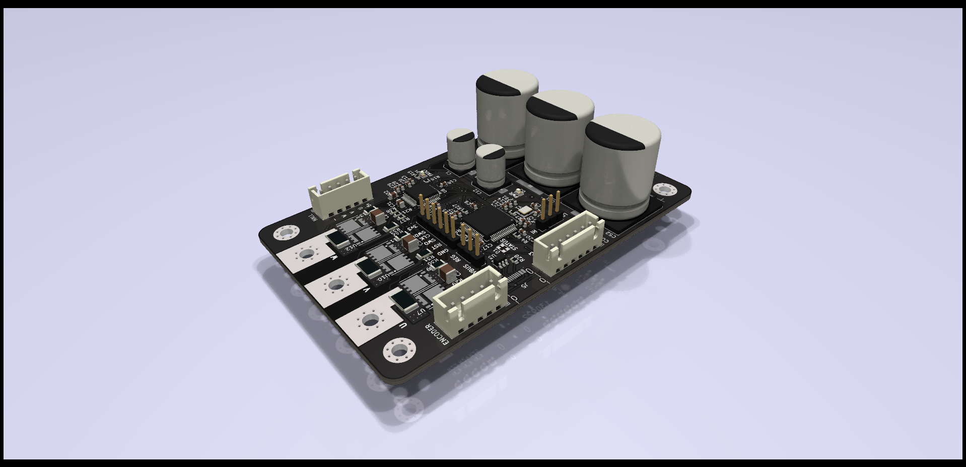
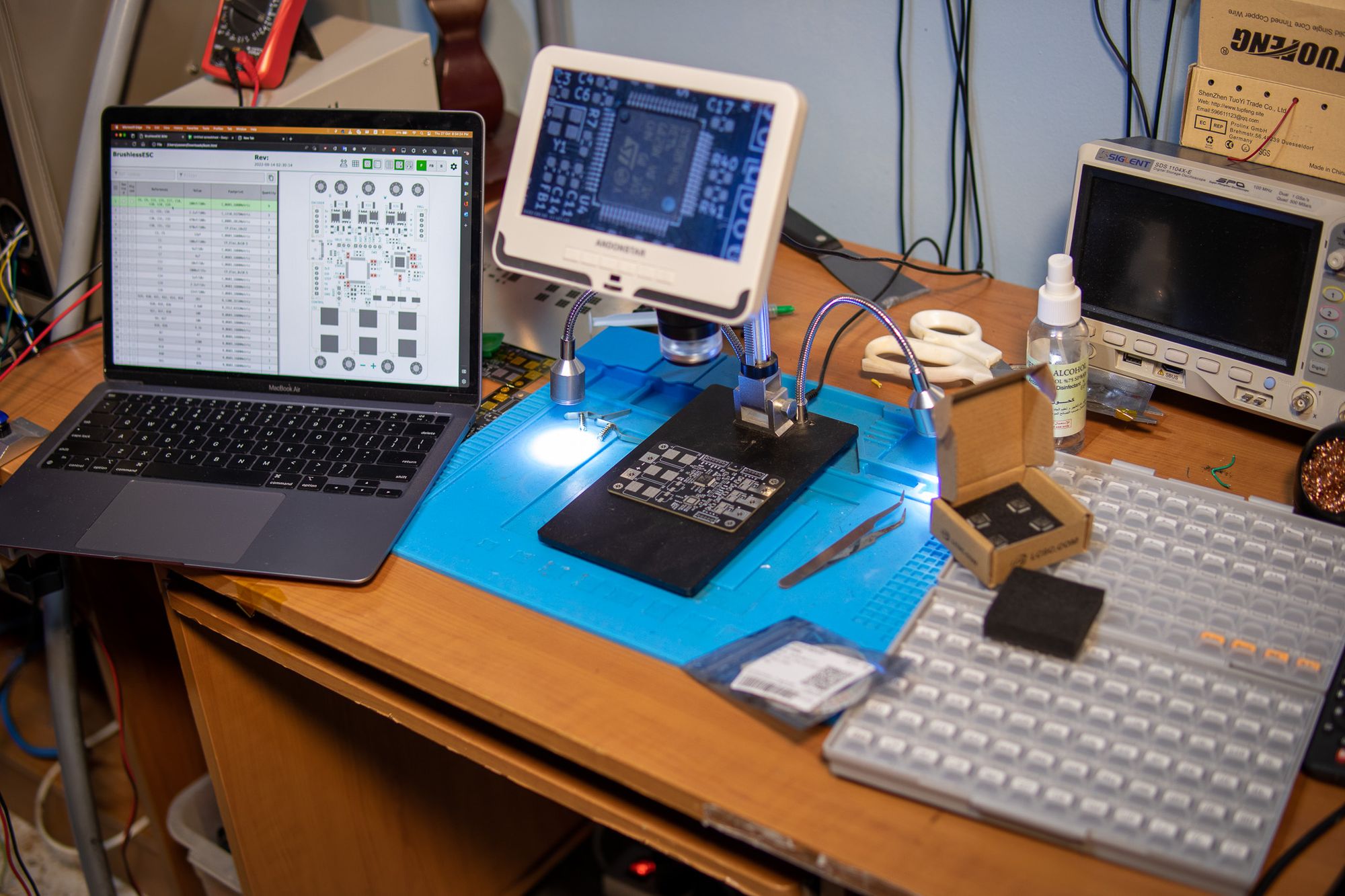
Designing The PCB
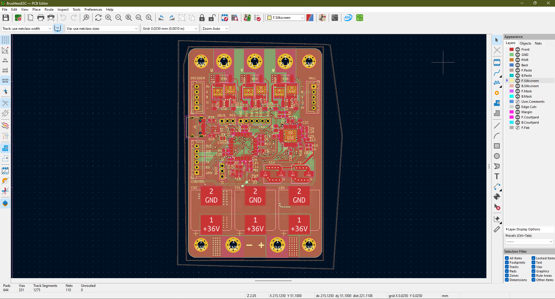
This is actually my first 4-layer PCB, and it was designed using Kicad 6. The two inner layers are primarily power planes, as advised by the TMC6200 datasheet.
Routing some of the traces wasn't easy, and I occasionally had to get creative. I also may have made some questionable choices along the way. There are many things that I would not repeat in fresh designs.
Some of the footprints I used were obtained from Ultralibrarian, which I suggest to anyone looking for part footprints. The only issue is that the majority of the footprints have duplicate courtyard/silkscreen lines, which drives the DRC crazy but is quite simple to repair.
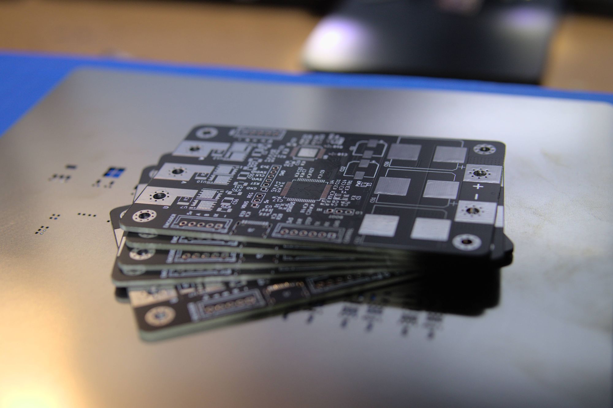
Ordering from JLCPCB
I ordered from JLCPCB for the first time, and I must say that the process went quite smoothly. They even fixed something for me.
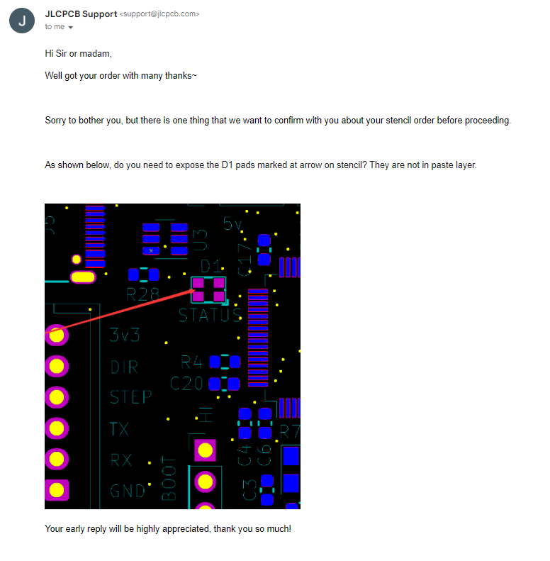
I apparently forgot to add the pads to the stencil layer when I created a custom footprint for an RGB LED that I used. The stencil would have ended up with no holes for the LED pads. They noticed that, got in touch with me to ask about it, and were nice enough to make the necessary corrections without requiring me to send new Gerber files.
Ordering The Components
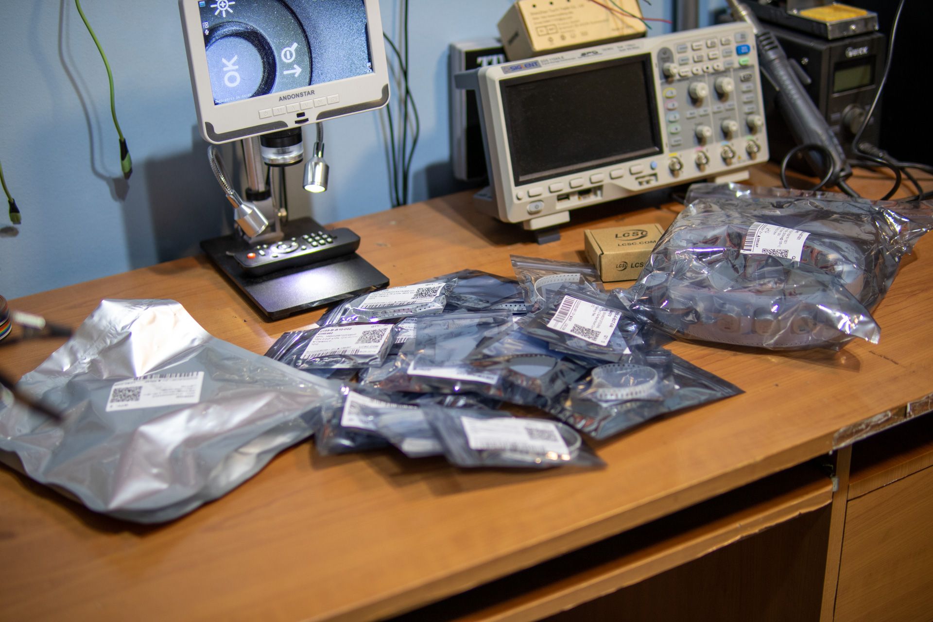
All the components were obtained from LCSC (partner of JLCPCB), with the exception of resistor and capacitor kits, some of those were from Amazon.
Due to where I live ordering from Mouser and DigiKey was mostly not an option or an annoying process that I did not want to go through.
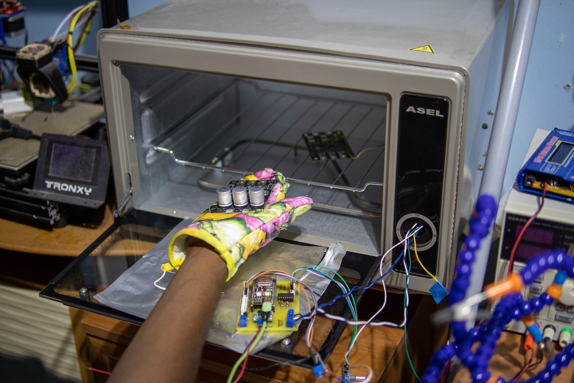
Reflowing the PCB
Since all the parts I utilized came from LCSC, I could have used JLCPCB's SMT assembly service, that would have been a bit pricy though as they demand an additional cost for any item that isn't on their list of "Basic Parts," which I had a lot of, because I wasn't designing with SMT in mind. However, that isn't the main reason. The main reason is that I couldn't possibly miss out on the experience and fun of doing this myself.
The process was a bit messy but simple: apply the solder paste using the stencil and a spatula, follow the diagram, and place each piece in its place.
Making multiple PCBs at once is preferable to doing one at a time, and while I didn't always need to use the microscope, it was helpful when I needed to make sure that the IC pins were properly aligned with the pads.
Afterward, I placed the PCB into my DIY Reflow Oven (which I will soon write an article about). Everything appeared to be going well, although I had to do several passes because some of the larger components, like the capacitors, were sucking the heat away and were not being properly soldered.
I was also concerned that I was dumping too much heat into the capacitors, but some datasheets appear to indicate that they can withstand it without harm. so fingers crossed.
So, does it work?
Well, sort of ... I still got a lot to figure out and some issues to fix.
This post is already quite long. The next post is going to be about debugging and programming the board and the issues I faced along the way.