TL;DR
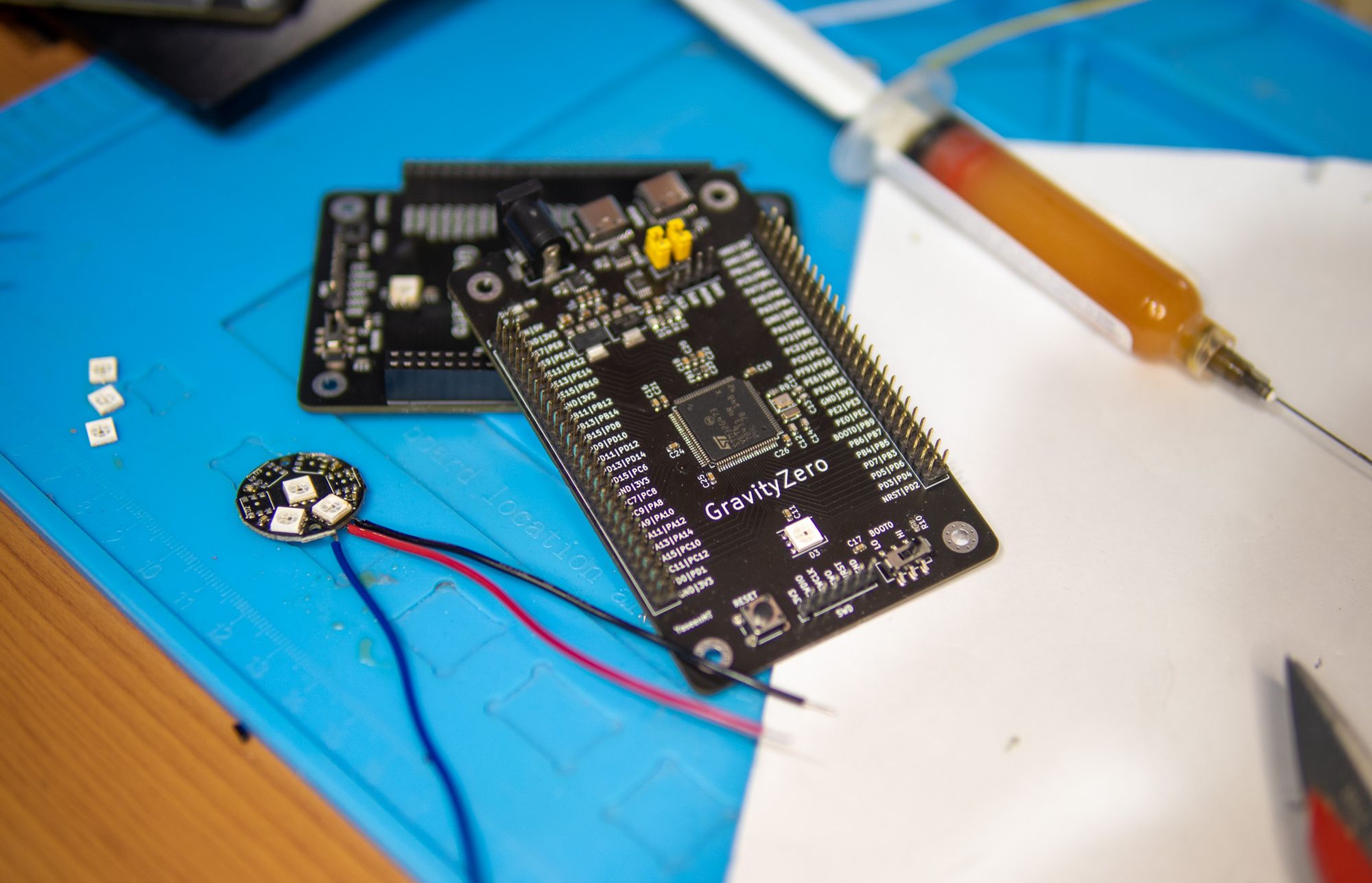
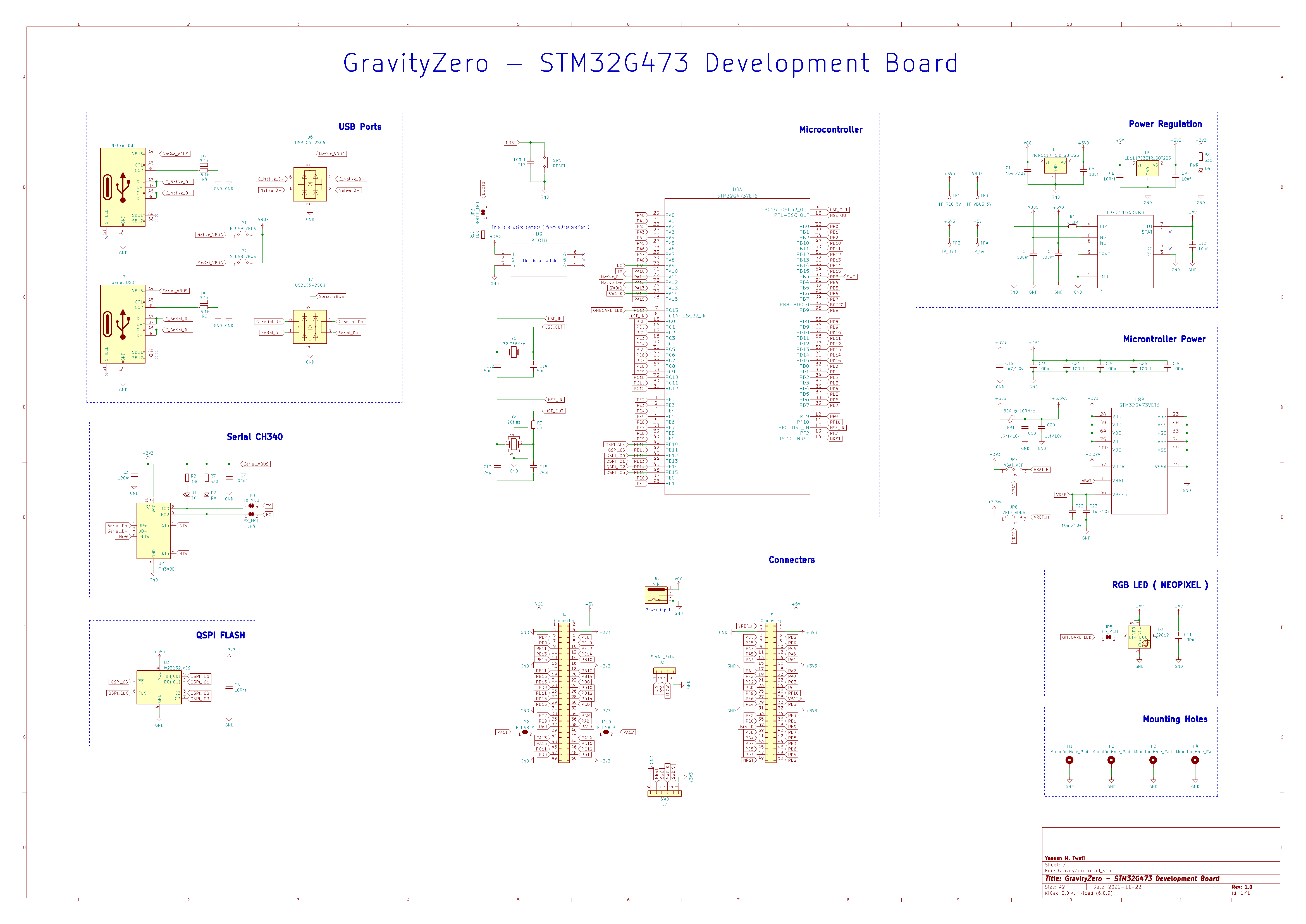
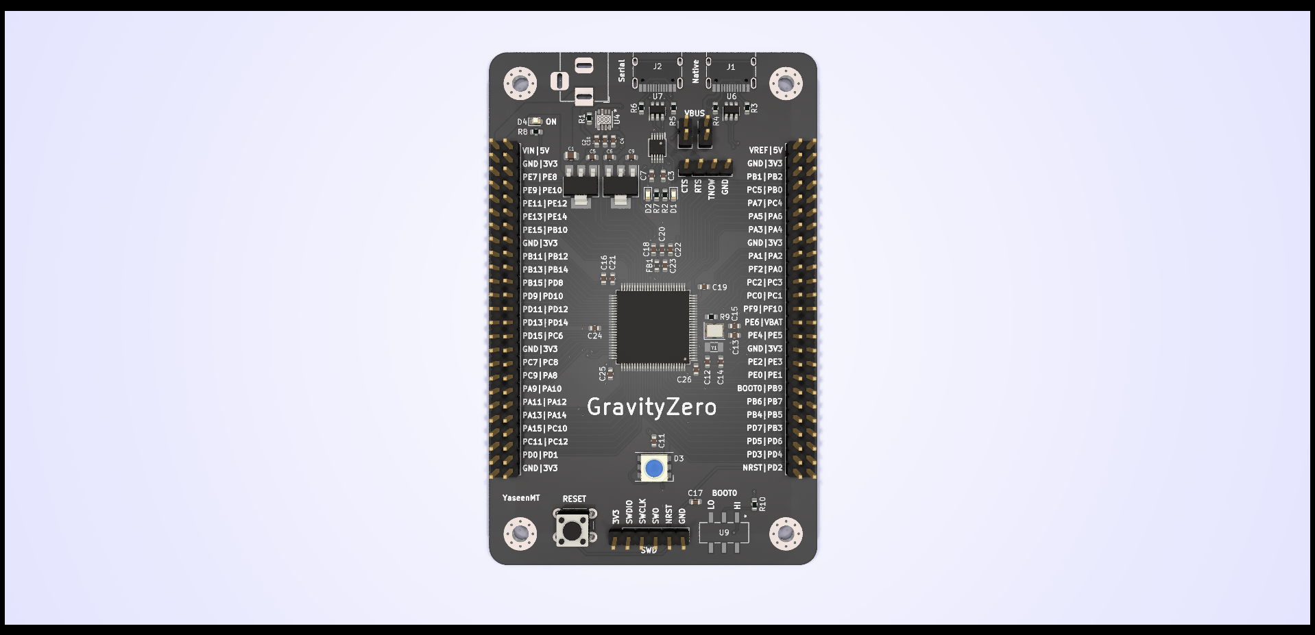
GravityZero is an Open Source STM32G473-based development board with two USB ports (Native & CH340 Serial), and access to nearly all the IO ports through the headers. alongside an onboard "NeoPixel" RGB LED.
Design Files are available on Github.
Why ?
Since I used the STM32F446 in my ongoing Brushless FOC Driver project, you could say that I've gone down the rabbit hole of exploring and understanding STM32 microcontrollers. I realized that I should probably slow down a bit, spend more time understanding the microcontroller properly, and then incorporate it into another design so that I don't make mistakes such as choosing less-than-ideal pins for a given task. thus the need for a development board.
I could have purchased one of the NUCLEO boards and experimented with that, but I like building things from scratch for the experience and the enjoyment of it, and it appears that ST/Mouser isn't authorized to export some of boards ( such as the NUCLEO-F756ZG ) outside of the US.
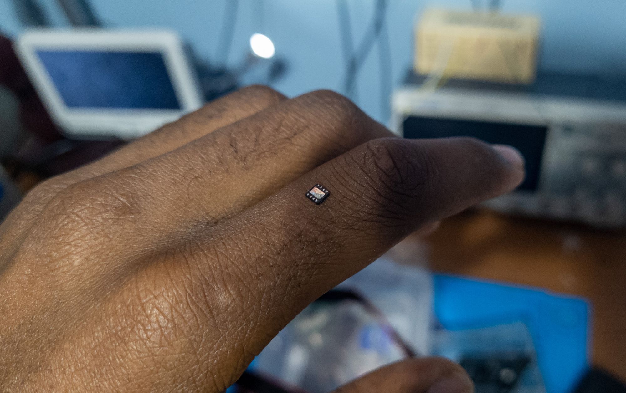
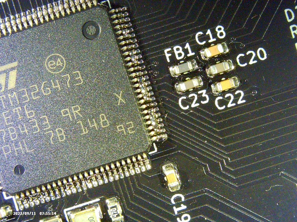
I went looking for a microcontroller and checking what was available and what wasn't. Since I already owned multiple STM32F series microcontroller, I wanted to experiment with another series. I came across the STM32G473 in its LQFP-100 form. It was certainly not cheap, but it was powerful, had all the plenty of features I wanted to try ( such as the CORDIC Engine ), and had enough GPIOs to work with.
Customizability
I wanted a development board that would let me freely experiment with the microcontroller's functionality without being constrained by permanently designating pins to a particular peripheral ( Ex: PA10 & PA9 for UART ).
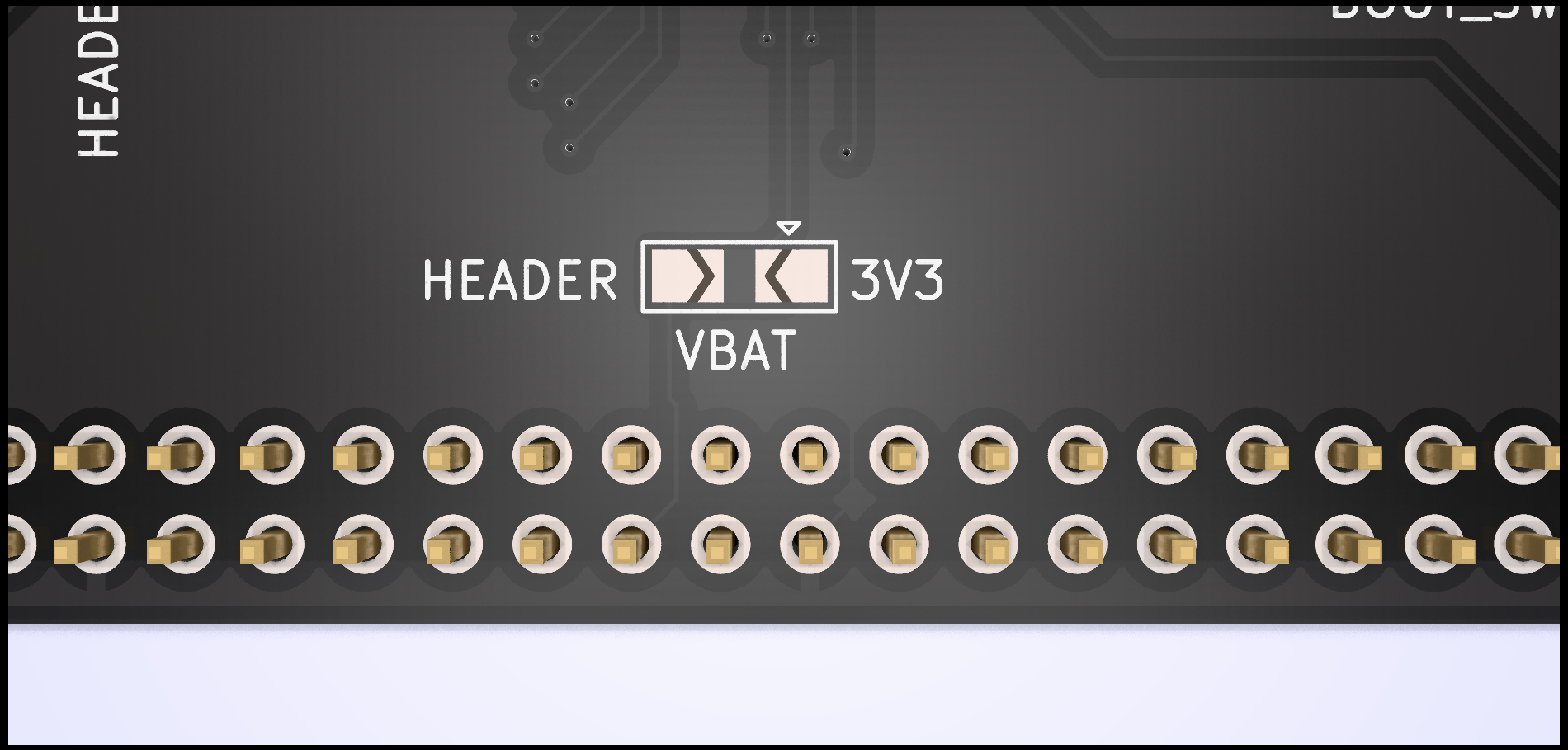
The board has a number of solder jumpers on the bottom to overcome this.
The only pins that are permanently connected are the HSE and LSE external clock pins.
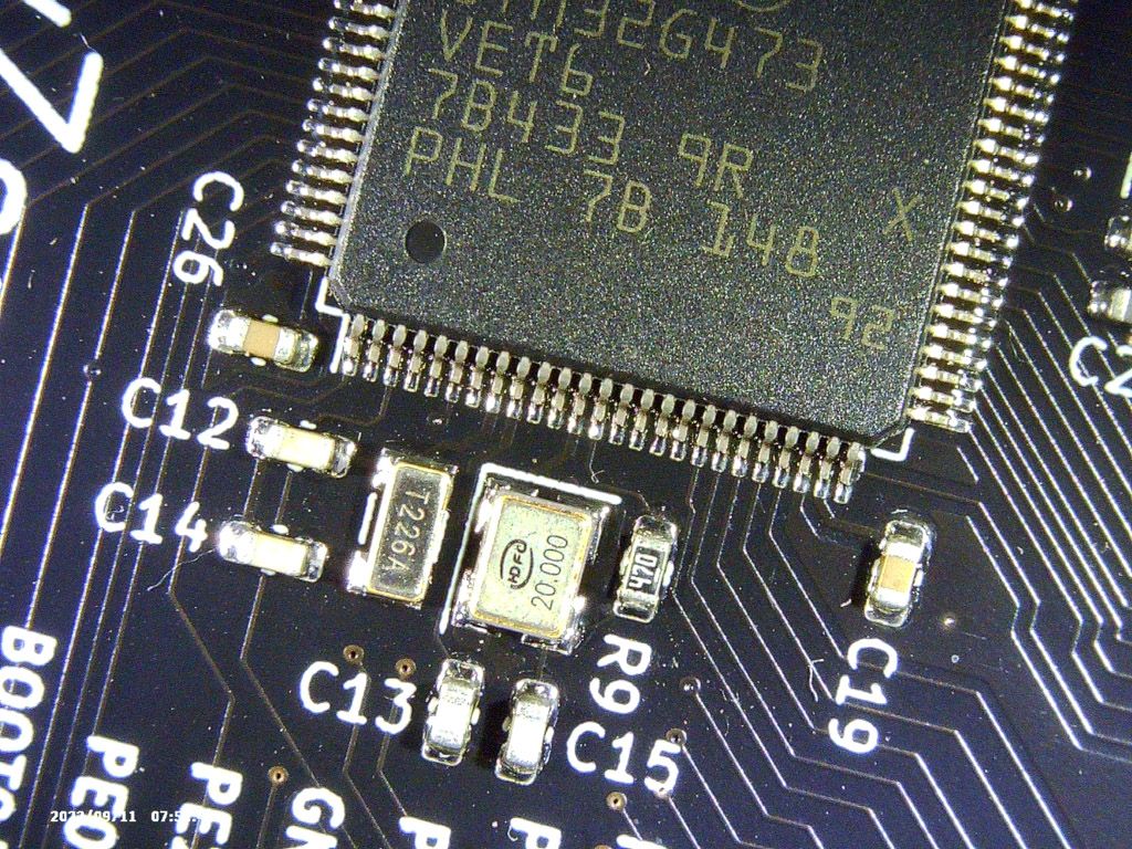
Microcontroller Clock
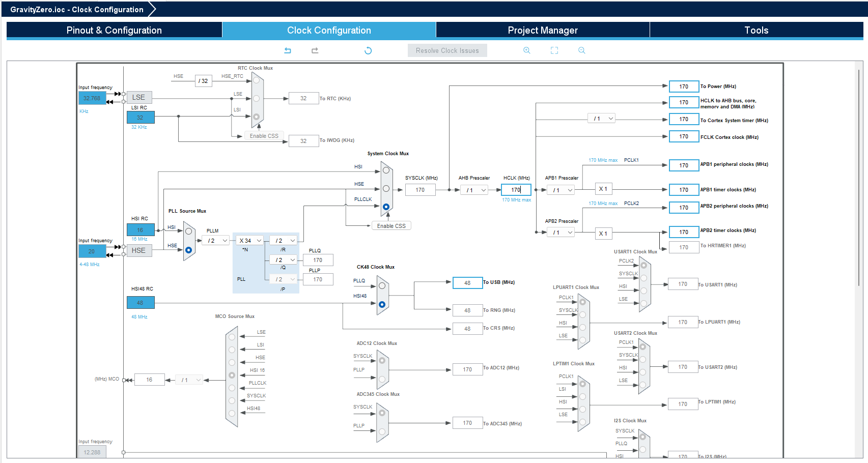
I've already mentioned that I selected the STM32G473, which I clocked at its maximum 170Mhz frequency with an external 20MHz crystal. The only issue is that this is an unusable clock for the USB peripheral. Which needs to be precisely 48Mhz, and there wasn't any Prescaler combination I could use to achieve that (I think?). This MCU, however, is one of those MCUs that are capable of crystal-less USB, meaning that it has an internal clock that is precise enough to be used for USB without the need for an external crystal, allowing me to change the main clock to anything I like without being worried. Great!
Power
The development board should be able to be powered though USB and/or an external DC source. Additional switching circuitry is required so that only either of them is active at any given time. I could have just ignored the switching part and allowed both power sources to turn on simultaneously, but doing so is risky. And as someone who has already burned their computer's front USB IO by doing some similar things xD. I won't take a chance.
The Arduino UNO board accomplishes this by using a few comparators and MOSFETs to select one of the power inputs.
I however chose to use the TPS2115A, a power switching mux IC made specifically for this purpose. I didn't really need to use this IC, but I was planning on using this IC in another project and thought that this would be a great testing environment for it.
The board also has two LDOs to step down the voltage to 5v ( if not powered through USB ) and 3v3.
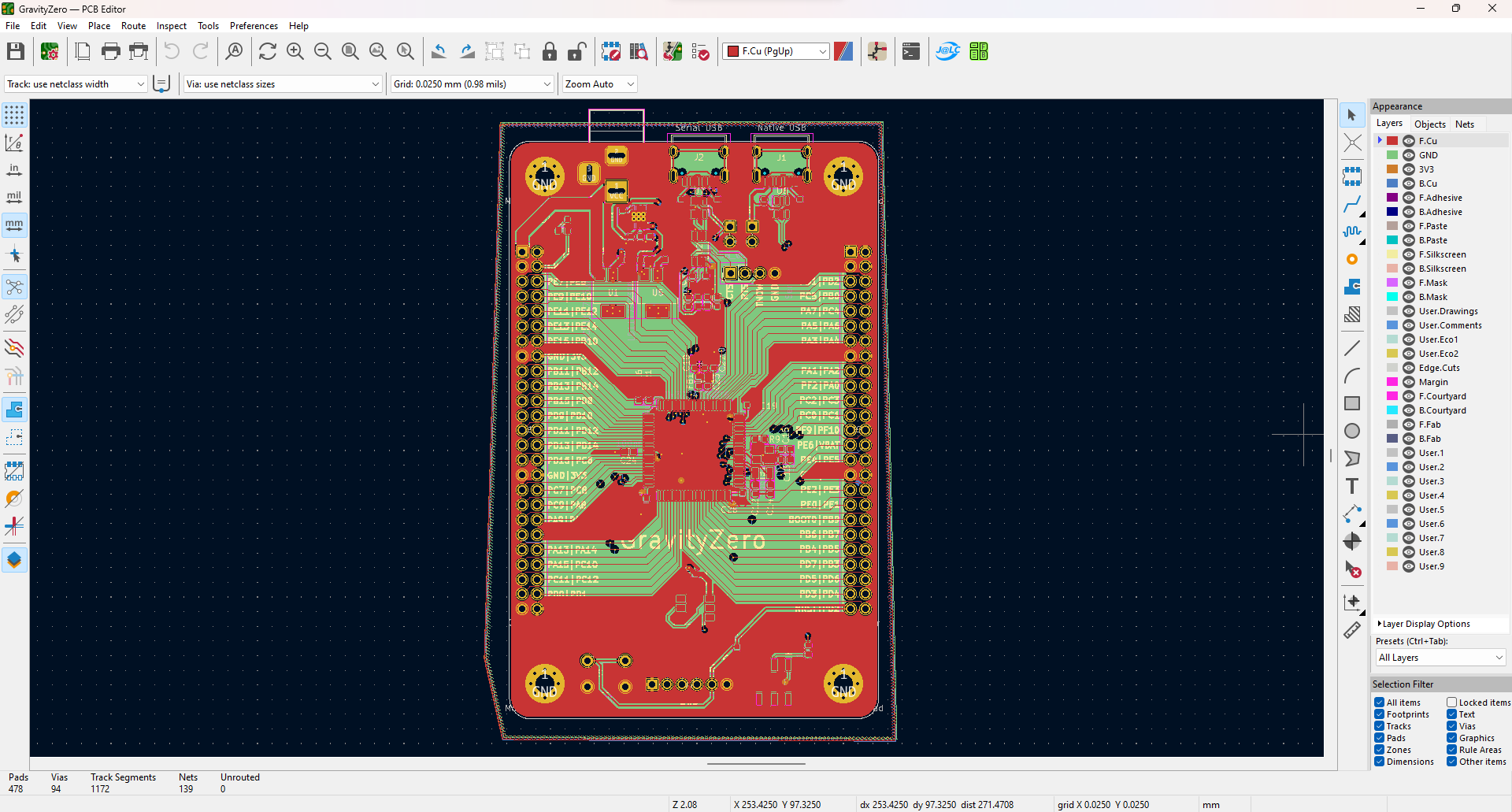
Designing - Why 4 Layers ?
The PCB was designed in KiCad 6. You could argue that 4 layers is better for EMI and gives me controlled impedance, but none of that matters much here. The only reason I chose 4 layers was because it made the routing easier. It was essentially a choice between spending considerably more time routing it on two layers or paying the additional $5 it costs for small PCBs on jlcpcb.com. I chose the latter option.
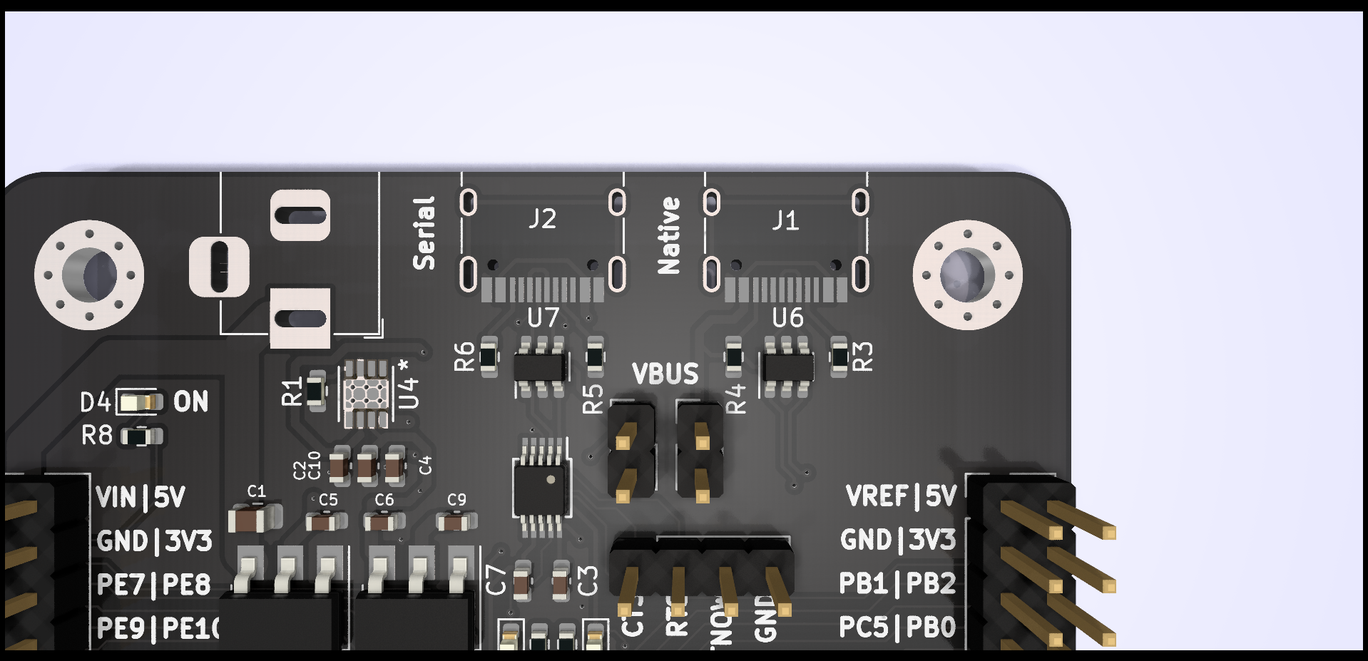
Two USBs ?
One of the two USB ports on the board is connected directly to the microcontroller's native peripheral, which is typically sufficient. However, the primary reason for having an additional serial USB is that the native USB disconnects anytime the microcontroller is reset. which can be annoying.
That second port is connected via a USB-to-Serial Converter, more precisely the CH340E. However it is only capable of serial communication and lacks any additional USB functionality. It can still be used to program the board through the built in UART bootloader.
I also exposed the unused pins of the CH340E ( CTS, RTS, TNOW ) for further experimentation.
GravityZero?
The board has nothing to do with gravity .. or zeros, I just like to give my projects codenames, and since I used a microcontroller from the STM32(G) family I chose a word that starts with G. and "Zero" refers to it being the first version ( there might be GravityOne and GravityTwo in the future .. who knows ).
Building & Reflowing
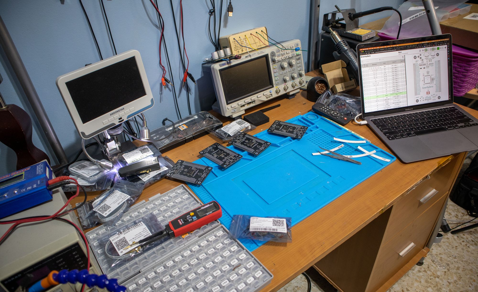
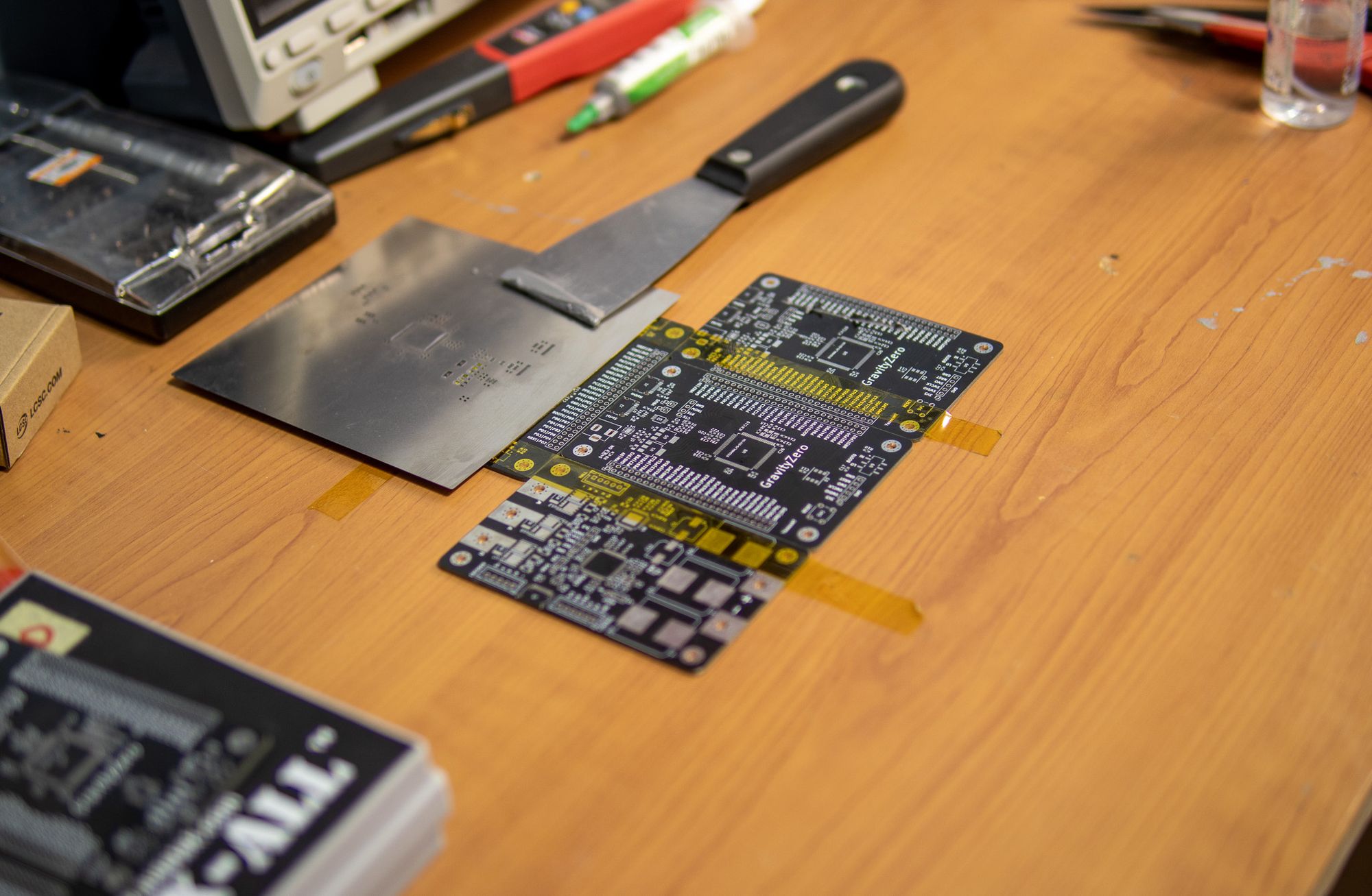
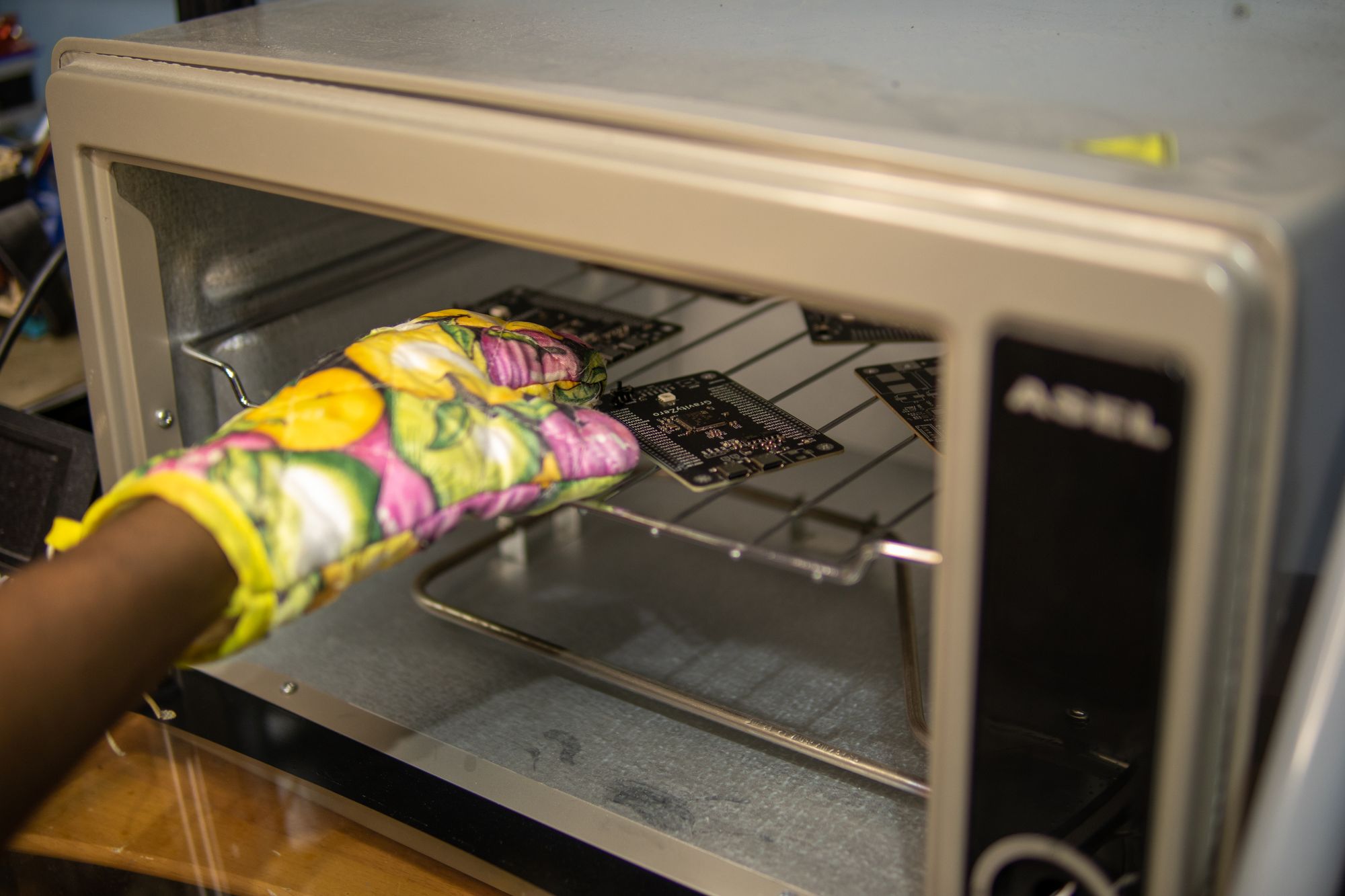
Upon receiving the boards and components, I started assembling four of them by applying solder paste using the stencil ( which I also ordered alongside them ), placing each component in its suitable position according to the interactive BOM, and then reflowing them in my DIY reflow oven. essentially the usual process, nothing special.
Programming & Uploading
In order to verify that code actually runs on it and that the clock speed is correct, I created a simple test program that simply toggled an IO ON and OFF, which allowed me to check the timing on my oscilloscope.
This was tested with both the STM32 HAL and the Arduino Framework through PlatformIO and both were successful.
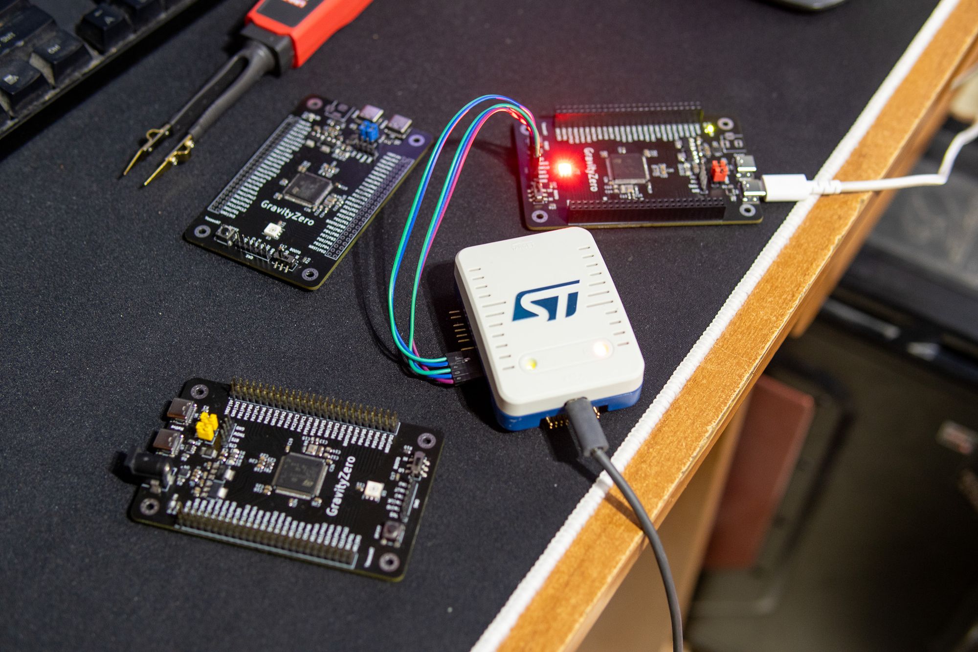
Three interfaces are available for uploading the program: Native USB via the DFU Bootloader, Serial USB via the UART Bootloader, and SWD via an ST-LINK ( or JLink .. etc ). All three passed my testing without any problems.
Building & Running MicroPython
Despite not being a Python person, its a powerful language and I still wanted to try running MicroPython on my board. This required building it from source since there were no supported boards based on the STM32G473. What was available however, was support for a board based on the STM32G474 which is a very similar microcontroller, you say that its the high resolution brother of the microcontroller I used ( it incorporates some high resolution timers ). That was a good starting point and I only needed to fiddle around with the clock & pin configurations.
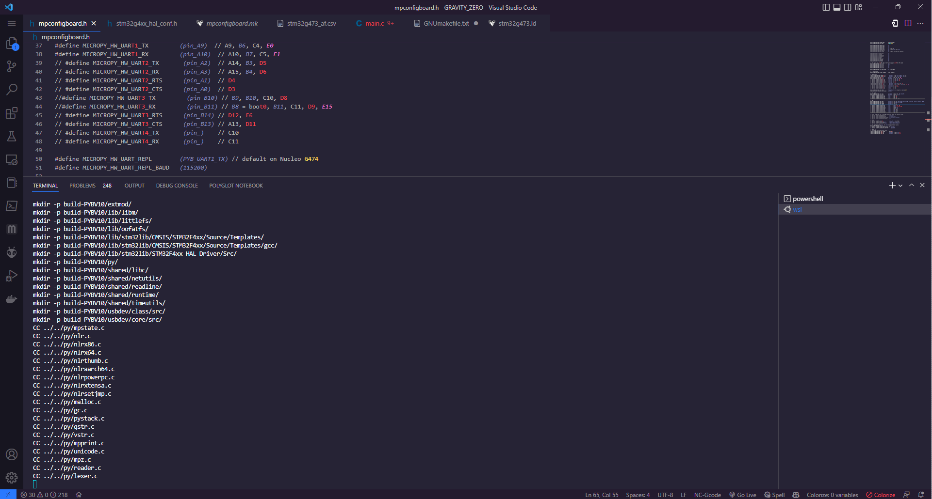
The build failed a few times, mostly due to USB related errors, the NUCLEO board I used as a starting point for the configuration doesn't expose a USB port, so it wasn't an issue for them and was probably never properly configured. Since I wasn't planning on using MicroPython for any real development, after 15 minutes of fiddling around, I just decided to compile without native USB support since I had the other serial USB. I'll revisit this issue in the future.
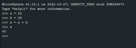
I uploaded ( downloaded ? ) the program to the board using the USB DFU bootloader through STM32CubeProgrammer, fired up a serial terminal, set the correct baud rate and reset the board ... and I was greeted by the beautiful python REPL :D.
This is all I wanted to achieve for time being, I'll figure out how to upload code and control pins on another day.
External Flash ( QSPI )
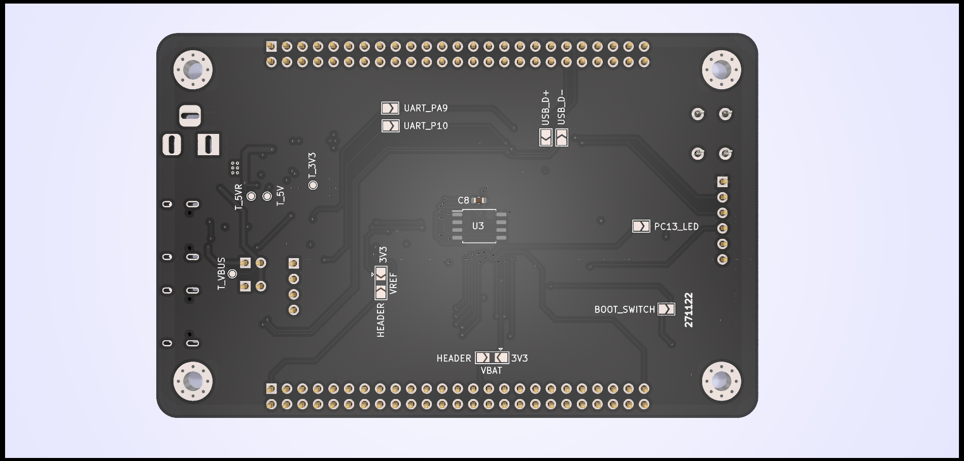
On the bottom side of the board, there is also room for a W25QXX Quad SPI External Flash IC, which may be left empty if not needed. I did solder it, but I haven't yet tried using it.
If I decide to use MicroPython again, this will be very useful as it's known to be storage demanding.
Problems & Mistakes
Reflowing
I had originally intended to make 4 boards, but I messed up one of them when applying the solder paste through the stencil. I then told myself that I would just fix any shorts after reflowing, and I did, but it seems that I missed something and ended up burning one of the boards, and now there is a permanent short between the 3v3 and GND lines. I'll try to solve it by replacing some of the board's components, however if the microcontroller is what's burnt, there wouldn't be anything I can do in the meantime as I do not have an extra microcontroller.
3 Boards is more than enough anyways ( assuming I don't burn anymore of them lol ).
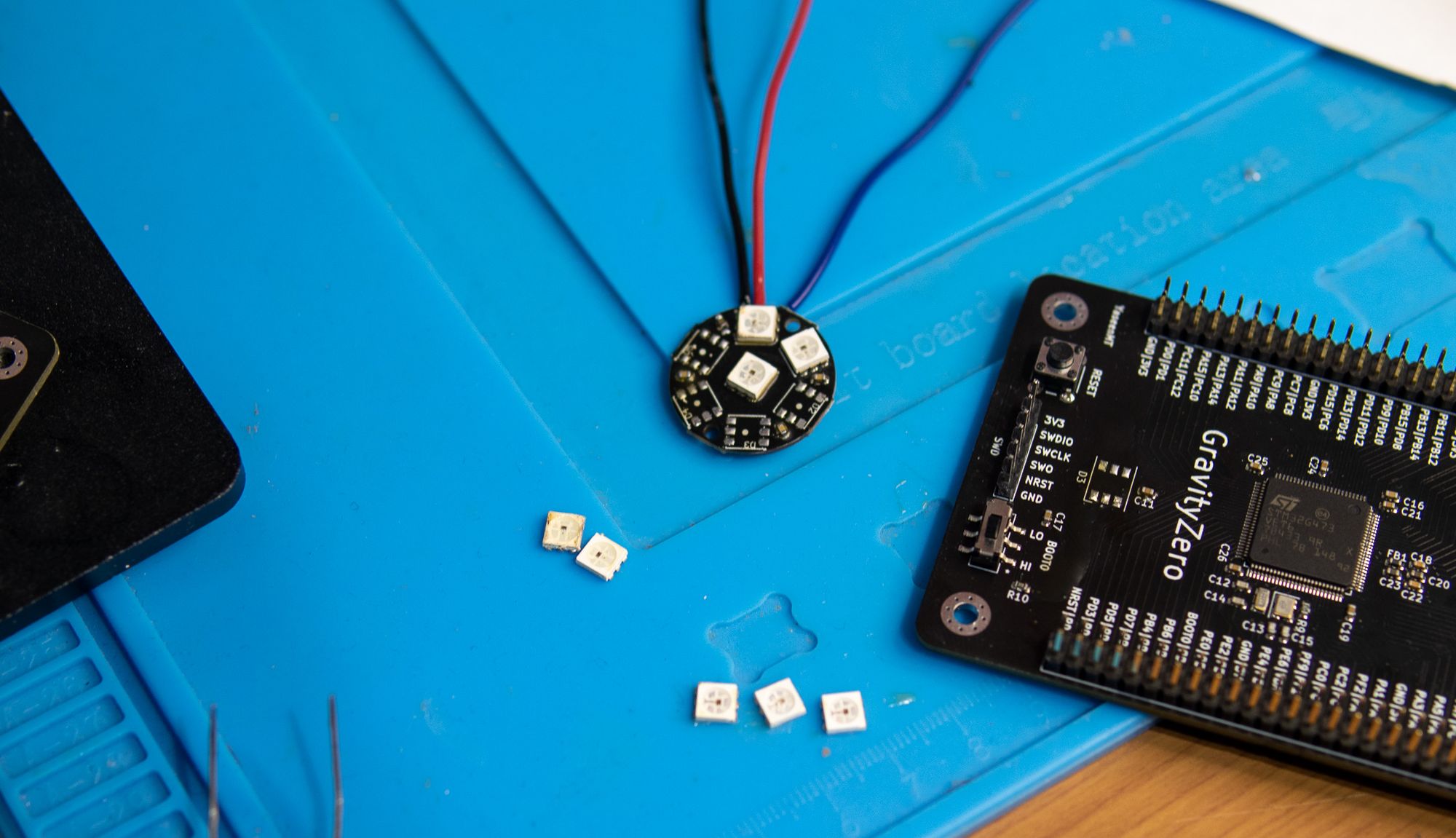
NeoPixel & PC13
Okay, to start, it isn't actually called a NeoPixel; NeoPixel is a trademark of Adafruit. It's an addressable RGB LED. And that one I ordered was the WS2812S, which did not work properly. After investigating, it turned out that this model requires 6-7v; It would turn on, but would not correctly respond to commands. and was more or less always white-ish.
Fortunately, I had a 5v module lying around, which I de-soldered the LEDs off and replaced the ones I had. After doing this, they started working correctly.
The other mistake is that the PC13 pin, which is connected to the LED, is not exposed through the headers. I apparently forgot to connect it.
The plan was for it to be accessible through the pin headers and have a solder jumper that allowed it to be completely disconnected from the LED if necessary. Oh well. I can live without it.
Conclusion
The board works as required and will be the foundation for many of my next projects.
Should you build one ? probably not, there are plenty of cheaper options available, however if you still want to make one the files are available on my GitHub.
Comments & Notes are appreciated.