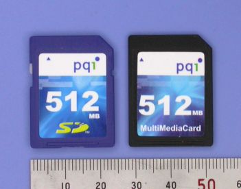
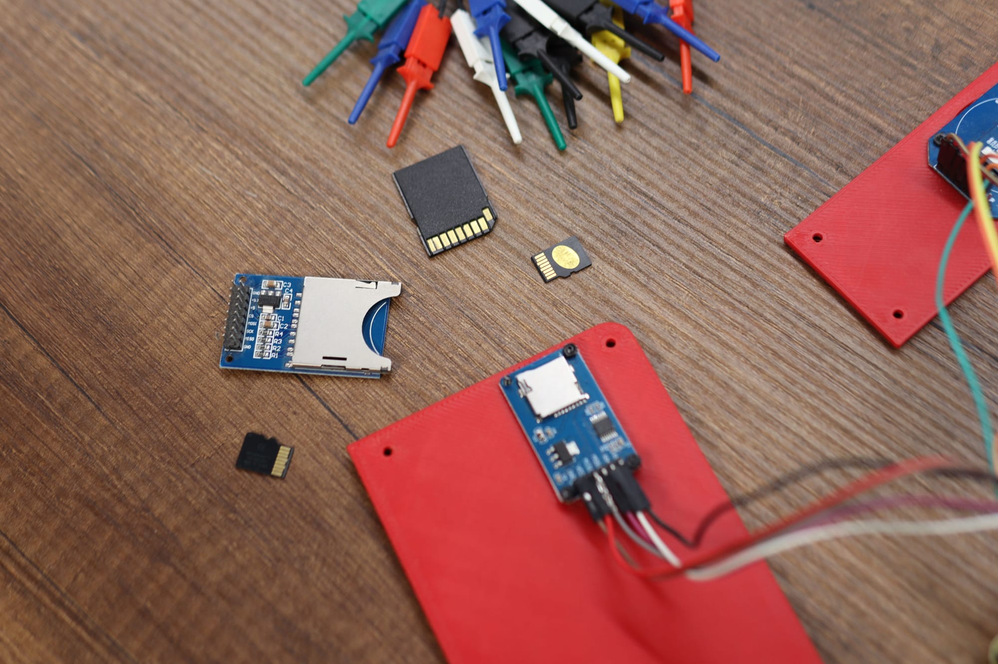
SD cards are a popular data storage option, especially in embedded systems. In a recent project, I needed to log some data onto an SD card. However, I hit the flash storage limit when I added any of the popular SD card libraries. Most of the remaining space was already being used by the LCD GFX library.
The reason these libraries tend to be so bulky is that most of their complexity comes from implementing the FAT file system—not the actual communication with the SD card. There are smaller libraries, like LittleFS, which might be worth trying (I think it’s smaller?).
But here’s the thing: I don’t need files, folders, or any of that. All I need is to log some raw data. So why not just write raw bytes directly to the SD card and worry about reading them back on the PC later?
Communicating with the card
So, how do we talk to an SD card? SD cards can be communicated with using two types of interfaces: SD mode and SPI mode. While SD mode is faster, it requires special hardware peripherals that we don’t have. Most microcontrollers, however, do support SPI, which is what we’ll be using.
If you want to dig deeper, you could dive into the SD card specification (400+ pages) to figure out how it all works. But luckily, there are plenty of useful resources online (linked at the end). Another option is to look at the source code of existing SD card libraries. I decided to do both—I reviewed the source code and used my logic analyzer to see what was happening in real-time.
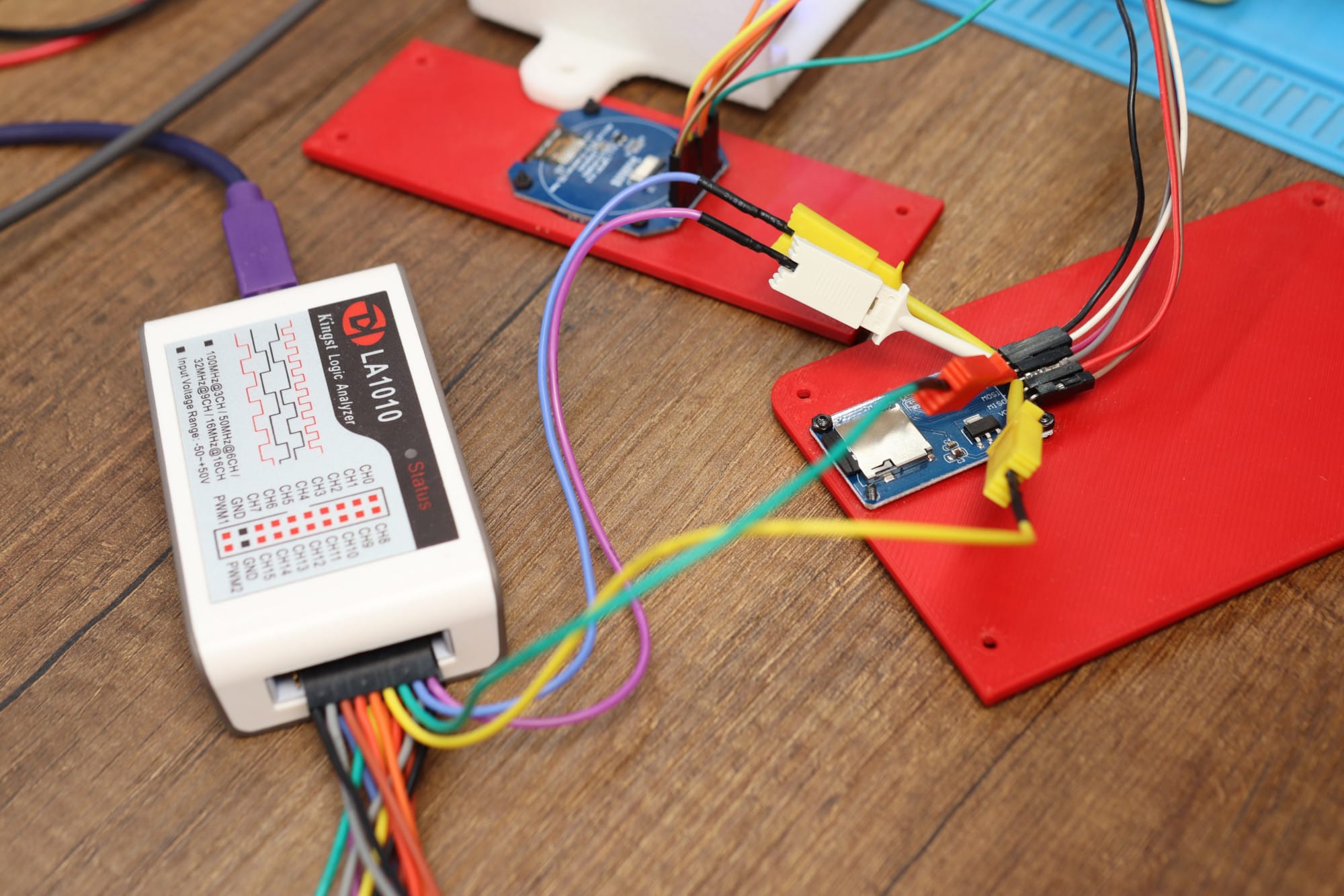
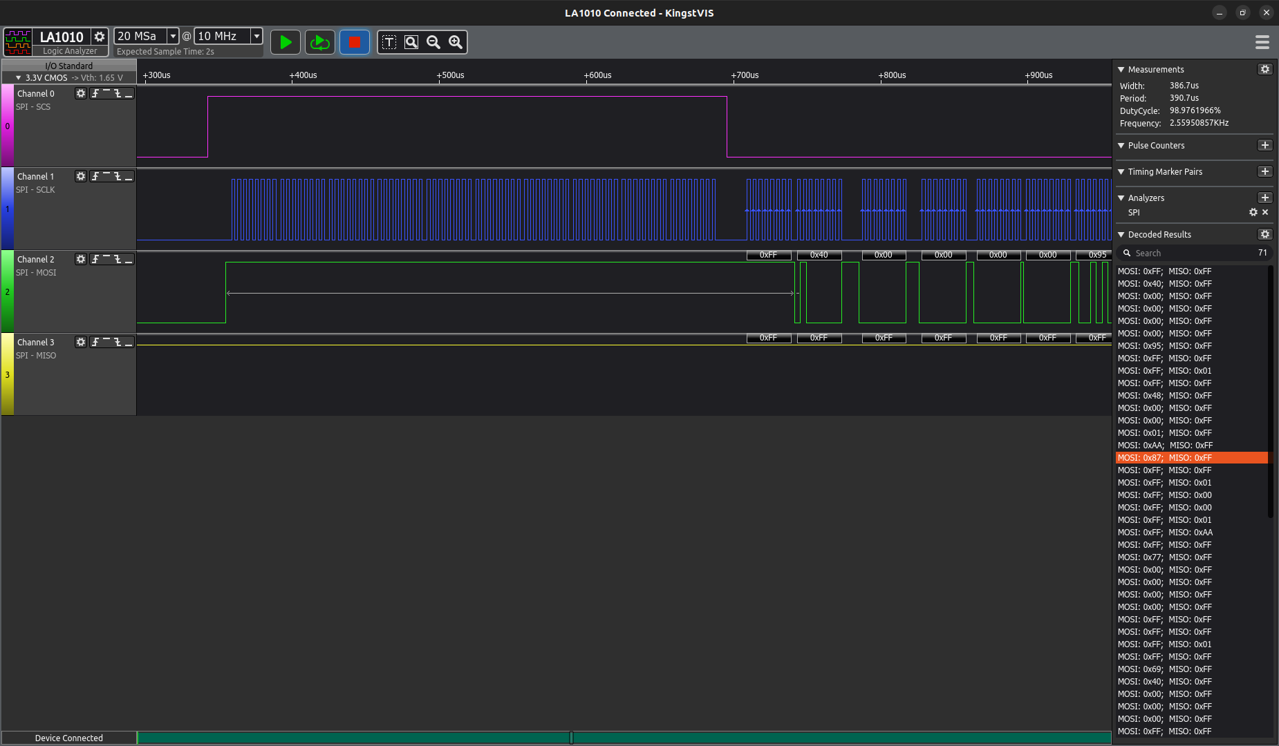
If you do the same, you might notice that there can be slight differences between libraries. For example:
- Some commands include "don’t care" bytes, and each library might handle these differently, which also affects the CRC at the end of the command.
- Some libraries don’t bother calculating the CRC to begin with unless it’s required.
- Others support multiple types of SD cards, or handle different versions of the SD card specification.
You get the idea—libraries may differ slightly depending on what features and card types they support.
This brings me to an important point: I’m keeping things simple. My goal is to do the bare minimum to get the card working. All I need is to initialize it and read/write some data. For simplicity, I’ll assume the card is a v2 card and ignore everything else.
If you’re curious about the different types and versions of SD cards, check out the resources I’ve linked at the end.
Getting ready
Let start by preparing the functions we will need to communicate with the card
Sending Commands
SD cards offer a range of commands, but we’ll only use a subset for basic initialization and data transfer.
| Command | Description |
|---|---|
| CMD0 | Reset the card back to idle mode. |
| CMD1 | Start initialization process. |
| CMD8 | Check voltage range. we don't really care about the voltage range, we are just using this command to make sure its a v2 card since this command doesn't exist on v1 cards. |
| CMD55 | CMD55 must be sent before sending an ACMD (Application Specific Command), more on ACMDs can be found in the linked resources |
| ACMD41 | Initializes the SD card in high-capacity mode (> 2GB) |
| CMD17 | Read a single block (sector) |
| CMD24 | Write a single block (sector) |
// The SPI clock speed must be below 400khz during initialization
SPISettings sdSpiSettings(250000, MSBFIRST, SPI_MODE0);

void send_card_command(uint8_t cmd, uint32_t arg, uint8_t crc)
{
    wait_card_busy();

    // SD Card Command Frame: [Command | Argument | CRC] (48 bits)
    // Command  => | start bit (always 0) | command bit (always 1) | 6 bits command index |
    // Argument => | 32 bit argument |
    // CRC      => | CRC7 (7 bits) | end bit (always 1) |

    SPI.beginTransaction(sdSpiSettings);

    SPI.transfer(0x40 | cmd); // 0x40 sets the command bit to 1

    SPI.transfer(arg >> 24);
    SPI.transfer(arg >> 16);
    SPI.transfer(arg >> 8);
    SPI.transfer(arg);

    SPI.transfer(crc);

    SPI.endTransaction();
}
Reading card response
Once we send a command, we need to read the response, which may arrive after a variable number of cycles. To handle this, we continue receiving data until we get a response that isn't 0xFF.
uint8_t read_card_response()
{
    SPI.beginTransaction(sdSpiSettings);

    // keep receiving bytes until we receive something that isn't 0xFF
    for (uint8_t i = 0; i < 10; i++)
    {
        uint8_t response = SPI.transfer(0xFF);
        if (response != 0xFF)
        {
            SPI.endTransaction();

            return response;
        }
    }

    SPI.endTransaction();
    return 0xFF; // no response, something is probably wrong
}
Waiting while the card is busy
The card can be busy at times, so we need to wait before sending another command. While this may not apply to all commands, we'll do it anyway to be safe.
bool wait_card_busy()
{
    auto start_time = millis();

    // wait until the card pulls the DO high ( we receive a 0xFF )
    // or until we time out after 300ms, I don't have a particular reason
    // for choosing 300ms as a timeout value other than that it was the
    // value used in the SDFat library.

    for(;;)
    {
        auto r_byte = SPI.transfer(0xFF);

        if(r_byte == 0xFF)
        {
            return true;
        }

        if(millis() - start_time > 300)
        {
            return false;
        }
    }
}
Initializing the card
First, we need to cycle the clock at least 74 times with the CS line HIGH. This isn’t typically required for most SPI devices, but it’s necessary for SD cards after power-up to switch them to native mode. We can accomplish this by sending any 10 random bytes over the bus.
bool init_sd_card()
{
    delay(300);

    digitalWrite(CS_PIN, HIGH);

    // at least 74 clock cycles after power up
    SPI.beginTransaction(spiSettings);
    for (uint8_t i = 0; i < 10; i++)
    {
        SPI.transfer(0xFF);
    }
    SPI.endTransaction();
Next, we must send the reset command (CMD0) to set the card into its idle state.
    digitalWrite(CS_PIN, LOW);

    // Reset the card ( CMD0 )
    send_card_command(0, 0, 0x95); // 0x95 is the pre-calculated crc
    if (read_card_response() != 0x01)
    {
        digitalWrite(CS_PIN, HIGH);
        return false;
    }
We can then verify that it's a v2 SD card by sending the voltage command and checking the response.
    // Check the voltage range ( CMD8 )
    // or more accurately, make sure this is a v2 card
    // we don't really care about the voltage rangee
    send_card_command(8, 0x01AA, 0x87);
    if (read_card_response() != 0x01)
    {
        digitalWrite(CS_PIN, HIGH);
        return false;
    }
Finally, we can initialize the card in high capacity mode. This might not work right away, we’ll retry a few times if necessary.
    uint8_t retries = 3;
    for (uint8_t i = 0; i < retries; i++)
    {
        // inform the card that the next command is an ACMD
        send_card_command(55, 0, 0x01);
        if (read_card_response() != 0x01)
        {
            digitalWrite(CS_PIN, HIGH);
            return false;
        }

        // Initializes the SD card in high-capacity mode (> 2GB)
        send_card_command(41, 0x40000000, 0x01);

        // if we receive 0x00 that means the initialization was successful,
        // otherwise we keep retrying
        if (read_card_response() == 0x00)
        {
            break;
        }
    }

    digitalWrite(CS_PIN, HIGH);

    // write an extra dunmmy byte after pulling the cs line high
    // this might be needed if you have other devices on the same
    // spi bus as the sd card.
    SPI.transfer(0xFF);

    return true;
}
If everything went well, the card should be initialized and ready to receive read/write commands.
Reading/Writing Data
Since this project is for data logging, let’s assume I have 64 bytes of data that I want to save at each interval.
struct data_point {
    // doubles are 32 bits on avr arduinos
    double sensor_1_value;
    double sensor_2_value;

    uint8_t the_rest_of_the_data[56];
};
SD cards have a 512-byte sector size, meaning we can only read and write in blocks of 512 bytes. Even if I only want to modify a single byte, I must rewrite the entire block. Normally, the file system takes care of this, but since we’re doing this manually, I have a few options for how to layout the data.
One approach is to group every 8 data points together and write them in one go, so I don’t have to keep reading and rewriting the entire 512-byte block.
Or .. I could take the "lazy" approach and write each data point into a block of its own. This is wasteful in terms of space, but let’s do the math and see how long would the card last with this approach.
Assuming I'm using a 32GB SD card and saving a reading every 5 seconds.
Bytes per day:
12 * 512 * 60 * 24 = 8,847,360 bytes
That means a 32GB card would last approximately 9 years ( 32 * 10^9 / 8,847,360 = 3,616 days ≈ 9 years )
Even a few months would have been enough for my use case.
Tracking the written bytes
To know where to write the next data point block, We need to keep track of how many blocks have already been written. We can use the first sector to store the current blocks count and increment it every time.
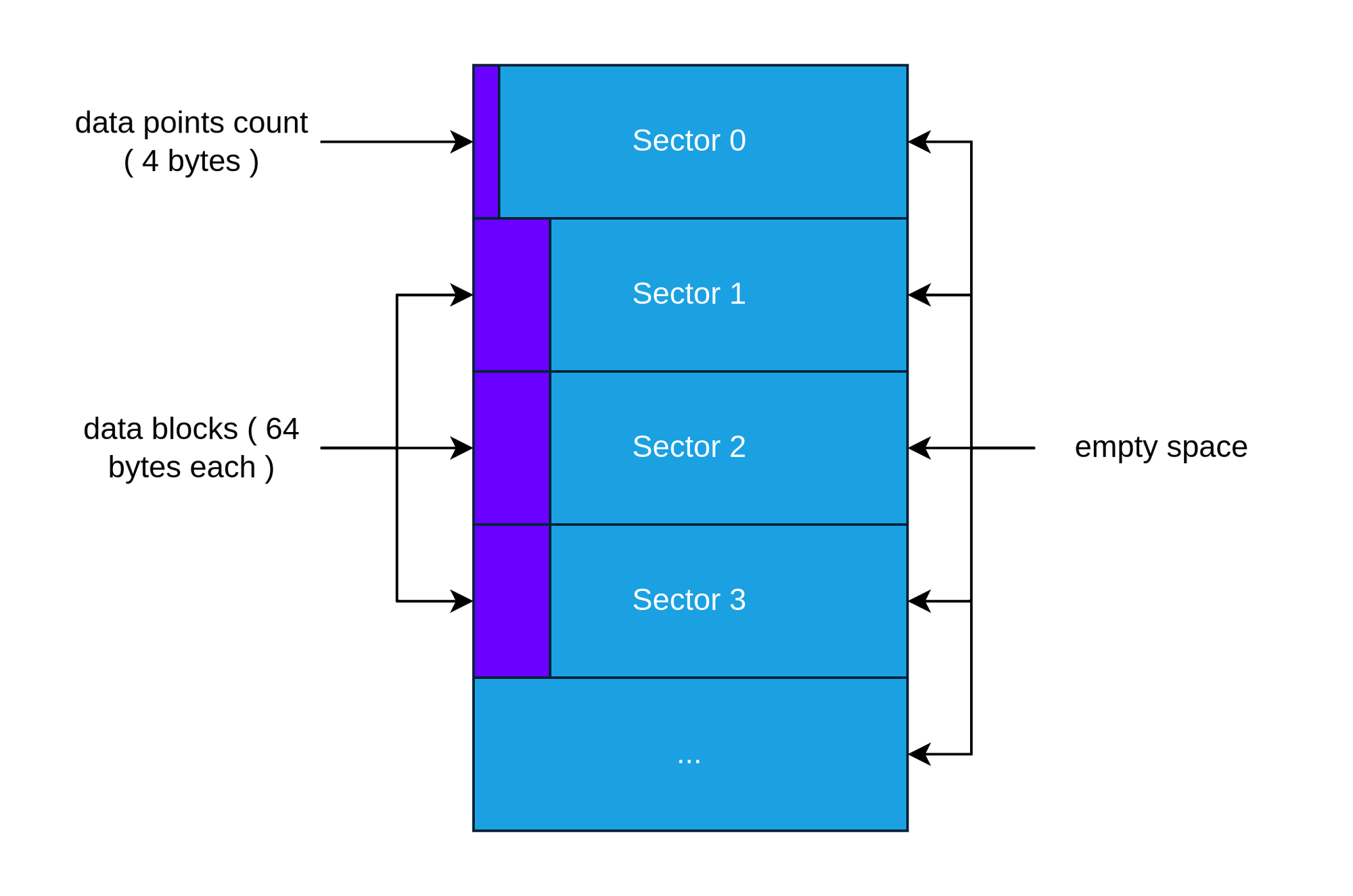
With that out of the way, let's dive into the implementation.
Reading a sector
bool read_card_block(uint32_t block_addr, uint8_t* buffer, uint16_t buffer_size)
{
    digitalWrite(CS_PIN, LOW);

    // send CMD17 ( read block ) with the block address as the parameter
    send_card_command(17, block_addr, 0x01);
    if (read_card_response() != 0x00)
    {
        digitalWrite(CS_PIN, HIGH);
        return false;
    }

    SPI.beginTransaction(sdSpiSettings);

    // we keep receiving bytes until we get the 'data token' ( 0xFE )
    while (SPI.transfer(0xFF) != 0xFE);

    // we need to read the entire 512 byte block regardless of if we need it or not
    // we are ignoring the bytes read once we have the buffer_size amount of bytes
    for (uint16_t i = 0; i < BLOCK_SIZE; i++)
    {
        uint8_t r_byte = SPI.transfer(0xFF);

        if (i < buffer_size)
        {
            buffer[i] = r_byte;
        }
    }

    // we aren't doing any CRC validation so we're ignoring the response
    SPI.transfer(0xFF);
    SPI.transfer(0xFF);

    SPI.endTransaction();

    digitalWrite(CS_PIN, HIGH);

    // write an extra dunmmy byte after pulling the cs line high
    // this might be needed if you have other devices on the same
    // spi bus as the sd card.
    SPI.transfer(0xFF);

    return true;
}
Writing a sector
bool write_card_block(uint32_t block_addr, const void* buffer, uint16_t buffer_size)
{
    digitalWrite(CS_PIN, LOW);

    // send CMD14 (block write)
    send_card_command(24, block_addr, 0x01);
    if (read_card_response() != 0x00)
    {
        digitalWrite(CS_PIN, HIGH);
        return false;
    }

    SPI.beginTransaction(sdSpiSettings);

    // Send the data start token
    SPI.transfer(0xFE);

    // we must write the entire 512 byte block
    // we fill the rest with zeros
    for (uint16_t i = 0; i < BLOCK_SIZE; i++)
    {
        if (i < buffer_size)
        {
            SPI.transfer(((uint8_t*)buffer)[i]);
        }
        else
        {
            SPI.transfer(0x00);
        }
    }

    // just a dummy crc
    SPI.transfer(0xFF);
    SPI.transfer(0xFF);

    uint8_t response = SPI.transfer(0xFF);

    // check if the data was accepted
    if ((response & 0x1F) != 0x05)
    {
        SPI.endTransaction();
        digitalWrite(CS_PIN, HIGH);
        return false;
    }

    // wait until the card is ready
    while (SPI.transfer(0xFF) == 0x00);

    SPI.endTransaction();

    digitalWrite(CS_PIN, HIGH);

    // write an extra dunmmy byte after pulling the cs line high
    // this might be needed if you have other devices on the same
    // spi bus as the sd card.
    SPI.transfer(0xFF);

    return true;
}
Now we should have everything we need to be able to write data readings into the card
bool save_data_point(const data_point* data)
{
// read the 4 bytes the first (0th) sector
uint32_t current_count = 0;
if (!read_card_block(0, (uint8_t*)¤t_count, 4))
{
return false;
}
// increment the count and write it back
current_count++;
if (!write_card_block(0, (uint8_t*)¤t_count, 4))
{
return false;
}
// write the data at the correct sector ( current_count + 1 )
if (!write_card_block(current_count+1, data, sizeof(data_point)))
{
return false;
}
return true;
}Example - Test Code
Let’s give it a try by saving the sine and cosine values for angles between 0 and 360 degrees.
First, we need to ensure that the first sector is set to 0. This can be done in code or by zeroing out the beginning of the SD card using a tool like dd on a computer.
void setup()
{
    Serial.begin(9600);

    while(!Serial);

    SPI.begin();

    pinMode(CS_PIN, OUTPUT);
    digitalWrite(CS_PIN, HIGH);

    if (!init_sd_card())
    {
        Serial.println("Card initialization failed");
        return;
    }

    Serial.println("Card initialization successful");

    // reset the first sector back to 0
    uint32_t initial = 0;
    if (!write_card_block(0, (uint8_t*)&initial, 4))
    {
        Serial.println("Could not reset the first sector");
        return;
    }

    // write the test data points into the card
    data_point example_data_point {};

    for (int angle = 0; angle <= 360; angle++)
    {
        Serial.println("Writing angle : " + String(angle));

        example_data_point.sensor_1_value = sin(radians(angle));
        example_data_point.sensor_2_value = cos(radians(angle));

        if (!save_data_point(&example_data_point))
        {
            Serial.println("Could not save data point");
            break;
        }
    }

    Serial.println("Data point saving completed");
}
Reading & Parsing the data on a PC
Since we're not using a file system, we can't simply open the SD card in the file explorer. Instead, we need to write a program that can read the raw bytes and parse the data exactly as we wrote it on the Arduino.
Important Note: If you're using Windows, be sure not to click "Format" if the system prompts you to do so. This will likely happen because the card doesn't contain a valid partition table.
Let’s start by cloning the card into a file. On Linux, this can be done using dd:
sudo dd if=/dev/sdX of=sd_card.img bs=4M status=progressusing dd to clone the card into a file where sdX is the sd card device
I'll be using Python to read the data from the .img file that we just cloned, save it to a CSV file, and plot it. Of course, the script will need to be modified based on the structure of the data we saved to the card. For now, I'll be reading two floats from the start of each sector (the sine and cosine values)
import struct
import csv
import sys
import matplotlib.pyplot as plt

def read_sd_dump_and_process(file_path, output_csv):
    SECTOR_SIZE = 512
    BYTES_PER_FLOAT = 4  # floats and doubles are 4 bytes on avr arduinos

    try:
        with open(file_path, "rb") as f:
            # Read the first 4 bytes of sector 0 to determine the number of readings
            first_4_bytes = f.read(4)

            data_points_count = struct.unpack("<I", first_4_bytes)[0]  # Read as little-endian uint32
            print(f"Number of data points: {data_points_count}")

            readings = [[], [], []]
            for i in range(1, data_points_count): # skip the 0th sector

                f.seek((i) * SECTOR_SIZE)

                # read the first 4 byte float ( sine )
                float_bytes = f.read(BYTES_PER_FLOAT)
                reading = struct.unpack("<f", float_bytes)[0]
                readings[0].append(reading)

                # read the second 4 byte float ( cosine )
                float_bytes = f.read(BYTES_PER_FLOAT)
                reading = struct.unpack("<f", float_bytes)[0]
                readings[1].append(reading)


            # plot the readings
            plt.figure(figsize=(12, 8))

            plt.plot(readings[0], marker='o', linestyle='-', label=f'Sine')
            plt.plot(readings[1], marker='o', linestyle='-', label=f'Cosine')

            plt.title("SD Card Data Plot")
            plt.xlabel("Angle")
            plt.ylabel("Value")

            plt.grid(True)
            plt.legend()
            plt.show()

            # save the data into a csv file
            with open(output_csv, "w", newline="") as csv_file:
                csv_writer = csv.writer(csv_file)
                csv_writer.writerow(["Sine", "Cosine"])
                for row in zip(readings[0], readings[1]):
                    csv_writer.writerow(row)

            print(f"Readings exported to {output_csv} successfully.")

    except FileNotFoundError:
        print(f"Error: File '{file_path}' not found.")
    except Exception as e:
        print(f"An error occurred: {e}")

if __name__ == "__main__":
    if len(sys.argv) < 3:
        print("Usage: python program.py <input_file> <output_csv>")
        sys.exit(1)

    input_file = sys.argv[1]
    output_csv = sys.argv[2]

    read_sd_dump_and_process(input_file, output_csv)
Results


That's it, we're done!
Notes & Possible Improvements
The code is written for Arduino but can be adapted for other systems by replacing the SPI calls with the platform’s specific SPI functions. I achieved my goal by doing the bare minimum required, but there are several potential improvements that could be made:
I achieved my goal by doing the bare minimum required, however there are multiple possible improvemnts that can be done
- Data validation: Currently, there's no check on the integrity of the data. You could consider using CRCs to validate the data, writing each block multiple times for redundancy, or adding a magic byte at the start and end of each block to ensure it’s a valid data block.
- Check available storage: It’s important to ensure there’s enough space on the card. This could be done by either hardcoding the card’s size or using the specific command to read the number of available sectors on the card.
- Improved error handling: Things can occasionally fail, and it would be useful to handle errors more gracefully. Reading the responses could help identify errors, and you could implement strategies like retrying the operation if needed.
- Improve Data Layout: We’re currently wasting 7/8 of the available space, which doesn’t really matter for our case, but it’s definitely something that can be improved. A simple solution could be grouping each 8 data points together. Alternatively, you could implement partial writes by reading the block, making modifications, and then writing it back. However, this would require using more RAM since you’d need to allocate 512 bytes of memory for the block.
If you have any other suggestions or improvements in mind, feel free to leave them below!
Resources & References
Here are some helpful resources and references that assisted me along the way.


