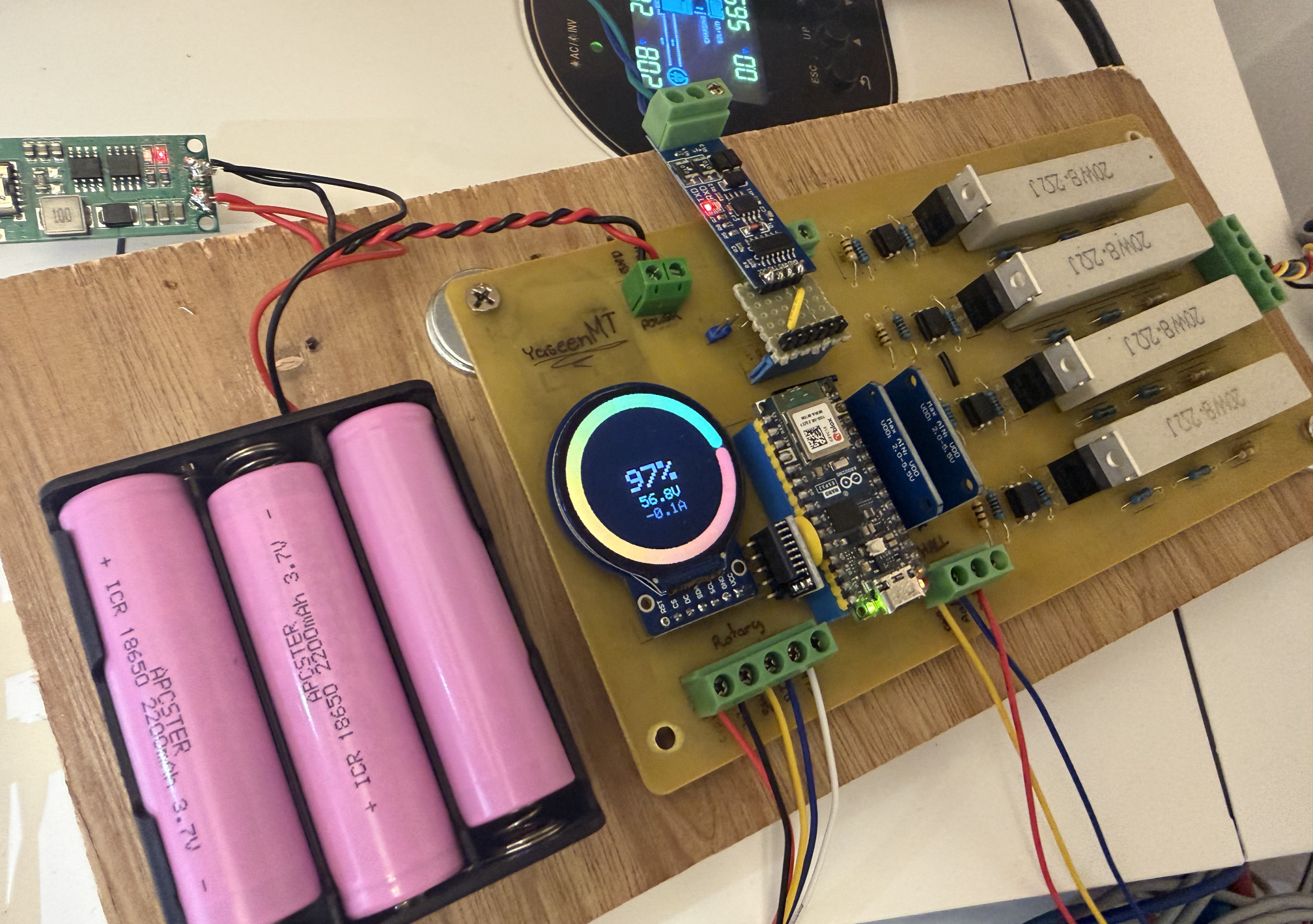
TLDR: I built a circuit that monitors a LiFePO4 battery pack and the current passing through it, to actually know how much charge is left. The board also talks to my inverter over CAN/RS485, pretending to be a real BMS, so the inverter can run in proper lithium mode instead of guessing. It's not what we normally consider a real BMS since it doesn't sit inline with the battery and can't physically disconnect it, so think of it more as a very opinionated monitor.
Why not just buy one? Nothing was available locally (i think), and I didn't feel like waiting for shipping.
I recently got a Growatt inverter system and a set of LiFePO4 batteries. Not the single, contained "all in one" units though, separate 12.8V batteries that I wired together to make the 48V the inverter wants. That works fine, but it comes with two problems.
Problem 1: No real SOC
The main issue is I can never actually tell how much battery I have left. Why not just measure the voltage? a LiFePO4 battery has a very flat discharge curve through the middle of its range, so 70% and 30% can look almost identical on a voltmeter.
Shouldn't the inverter already know this? Well not really. Mine is set to "User Defined" mode rather than Lithium, because Growatt requires an actual BMS connection to unlock Lithium mode. In User Defined mode, the inverter has no real SOC tracking and doesn't even know the battery's capacity, it just watches the charge current and a couple of fixed voltage points.
The proper fix is coulomb counting: actually track the current going in and out over time and keep a running total, instead of guessing from voltage.
Problem 2: No cell balancing
Each 12.8V battery has its own BMS internally (since it's really 4 cells in series), but there's nothing balancing the pack as a whole. Over time the four batteries drift apart, which either damages them or means you lose usable capacity as one hits its cutoff before the others.
The Circuit
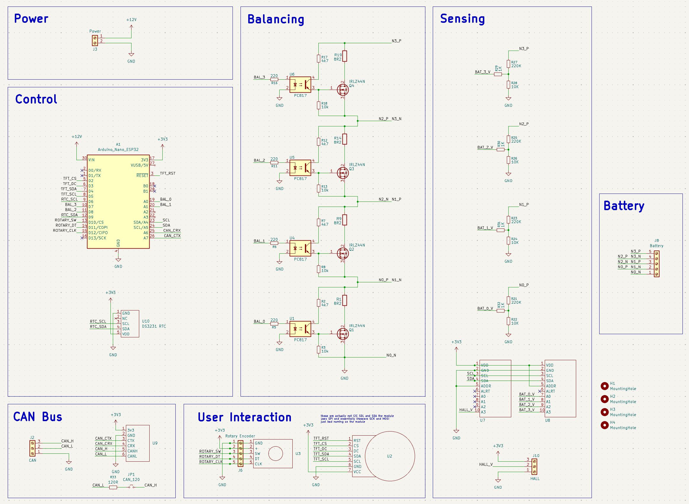
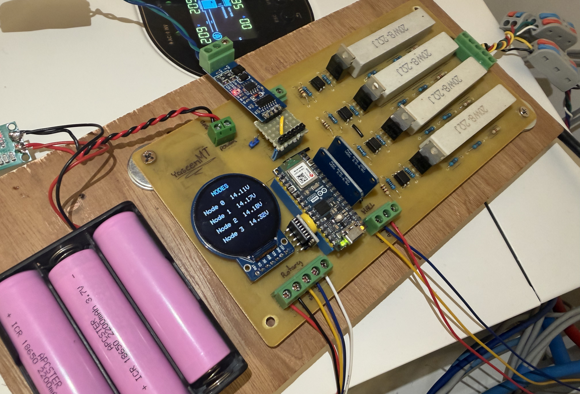
The whole thing is built around an Arduino Nano ESP32. Not because it was the best or cheapest option, but because it's what I had on hand that could do the job.
The whole thing is built around an Arduino Nano ESP32. Not because it was the best or cheapest option, but because it's what I had on hand that could do the job.
Current measurement & ADCs
A WCS1500 Hall sensor handles bidirectional current sensing, contactless, no shunt needed. ESP32's own ADC isn't great, so two ADS1115s handle the actual readings instead, one for the four battery tap voltages, one for the Hall sensor's output.
Balancing resistors
Balancing bleeds the leading battery through a 20W, 8.2 ohm resistor, duty cycled since running it continuously at a full 14.6V would push it past its rating. Each battery sits at a different voltage relative to the ESP32's ground, so the MOSFETs go through optocouplers instead, keeping the control side isolated from the floating switching side.
Power
Couldn't find a 60V+ buck converter locally either, so the board runs off a USB wall wart instead of the pack itself, backed by a small 3S Li-ion pack that takes over if that power drops. That backup matters since losing this circuit means the inverter loses its BMS and disconnects, assuming something's gone wrong.
Inverter communication (CAN/RS485)
Designed for CAN, but issues with my transceiver pushed me to an RS485 TTL converter instead. More on that below.
RTC
A small battery backed RTC keeps real time across power loss, so logged data stays meaningful even without WiFi to grab the time from.
User control
A round TFT and rotary knob drive a few screens (SOC, battery voltages, charge settings), plus a small web UI over the ESP's own access point mirroring the same info with graphs.

The PCB
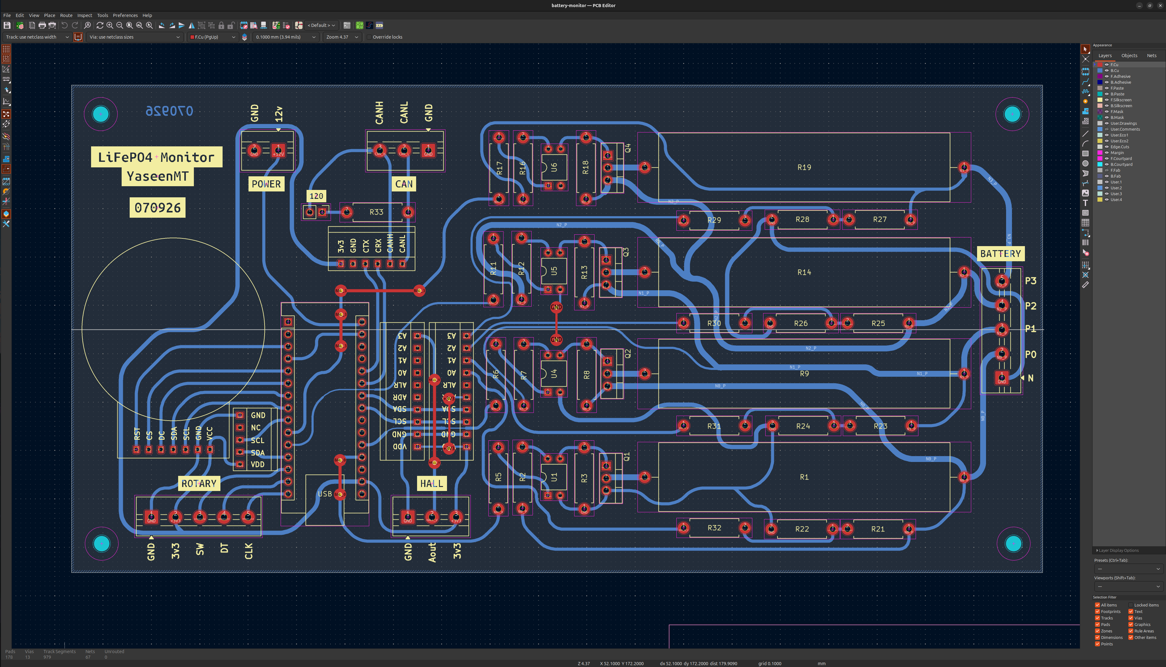
Routed in KiCad, built to be etched at home rather than ordered, so it had to be single layer with some tighter than usual constraints. Made using the toner transfer method and etched in ferric chloride.
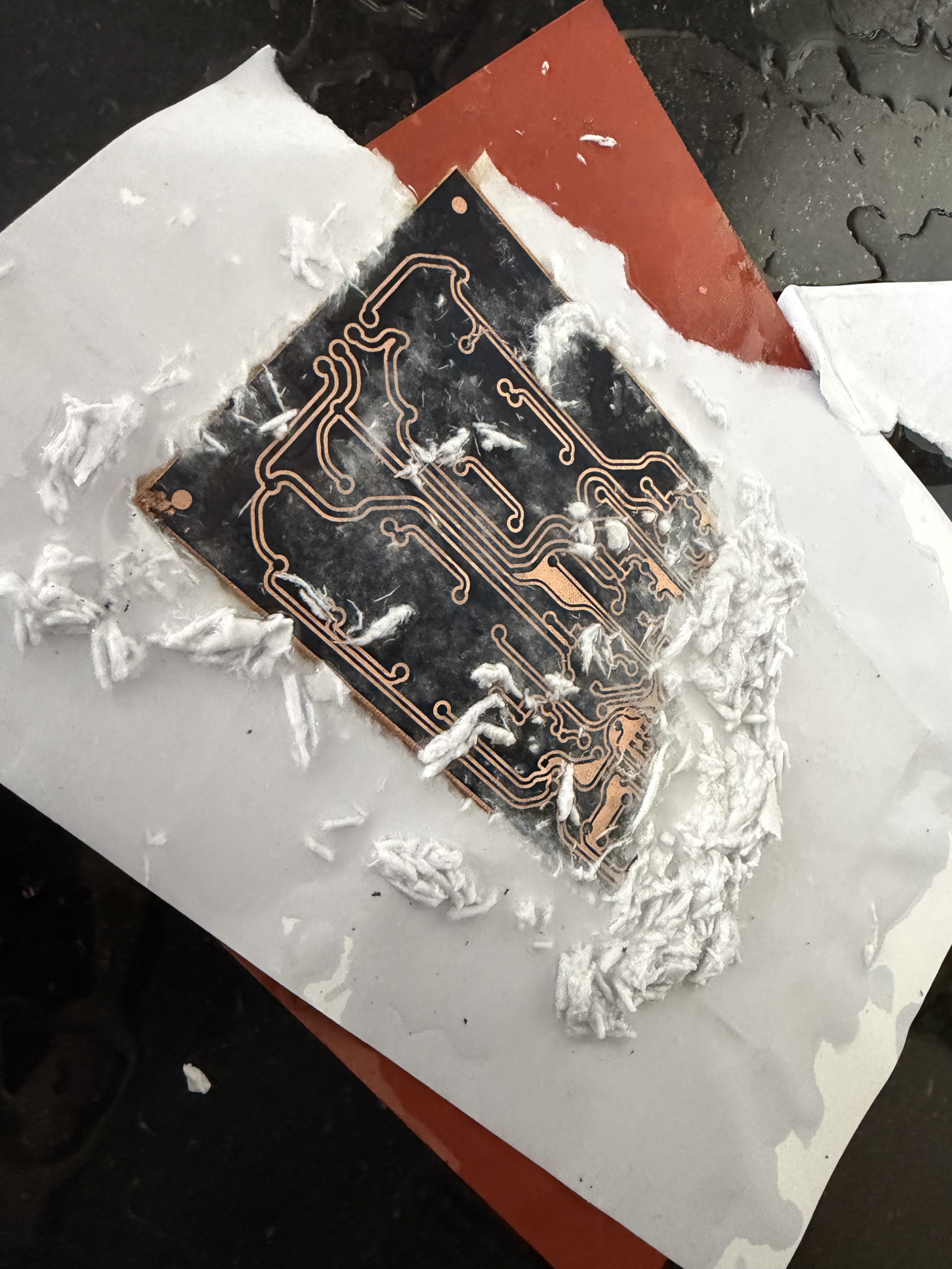

Toner Transfer & Etching
Communicating with the Inverter (Pylon Protocol)
The Growatt supports both CAN and RS485 for BMS communication, each with a handful of selectable protocols. The one that matters here is Pylontech's, since it's the one the DIY solar community has actually reverse engineered and documented, and Growatt happens to support it too. On my specific model that's protocol 52 for CAN, or protocol 02 over RS485.
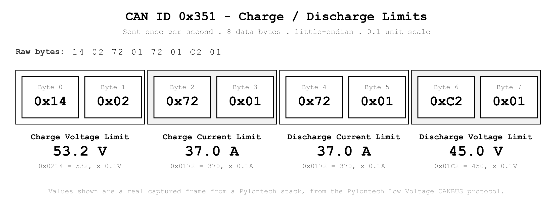
I originally went with CAN, since it's the more common choice for this sort of thing, wired up an SN65HVD230 transceiver, and got absolutely nothing back. Chased that down for longer than I'd like to admit,before finally tracing it to a dead transceiver chip.
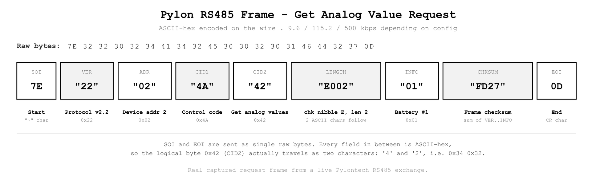
Rather than buying a replacement, I had the parts for RS485 sitting around already, so that's what actually ended up in the working version. Both protocols carry roughly the same information: charge and discharge voltage/current limits, SOC, and some alarm flags, just over different wires and at different baud rates.
The Logic
A few things the monitor actually needs to do:
Track SOC. Pure coulomb counting drifts over time, so it gets reset against two voltage anchors instead: 58.4V as a "fully charged" point, and a lower voltage point near empty. Since LiFePO4's curve is only steep enough to be useful near the two ends, these are the only two spots where voltage is trustworthy enough to correct against. The Hall sensor's zero point also gets recalibrated automatically whenever the system's been idle for a while, since a small offset error there is the main way this kind of coulomb counting quietly drifts.
Decide when to balance. Rather than bleeding current constantly, it only kicks in near the top of charge, when one battery's voltage pulls far enough ahead of the others, and only while actually charging. Balancing during discharge would just be wasting capacity you already paid for.
Talk to the inverter. Periodically packages up voltage, current, SOC, and limits into whatever the Pylon protocol expects, and sends it off (in the rs485 version of the protocol, the inverter is the master and is what periodically requests information that we reply with).
One thing I'm still working through: the inverter doesn't seem to resume charging until the reported SOC drops a fair bit below full, rather than the moment it dips even slightly. My guess is that's deliberate, to avoid rapidly cycling on and off, but the inverter's own idle draw (a few hundred mA) slowly bleeds the pack down in the meantime, so it ends up doing a small, pointless charge cycle every night just to make up for its own overhead. Planning to compensate for this by reporting a small nonzero charge limit near the top instead of cutting it to zero, so the inverter can trickle in just enough to cancel that out.
Why This Isn't a BMS
Technically it is a battery management system, but not in the way people usually mean it. It can't cut the battery off, since it doesn't actually sit inline, current is only sensed through a Hall sensor clamped around the cable. The best it can do is complain loudly to the inverter and ask it to disconnect on its own.
Every choice here, the parts, the protocol, even switching to RS485 partway through, came down to what I had on hand or could get locally. If you're trying to solve the same problem, I'd honestly just buy a proper BMS if you can get one. This was more about building something that worked with what was already in front of me.